I am a Seattle native who enjoys skiing and swimming and sailing. My passsion for engineering began as a child with audio and lighting systems and has grown into a love for energy and transportation systems. I aim to tackle impactful, challenging problems in sustainable technology, energy and education.
Scroll on for a look into some of my projects, or click a menu item to learn more and contact me!
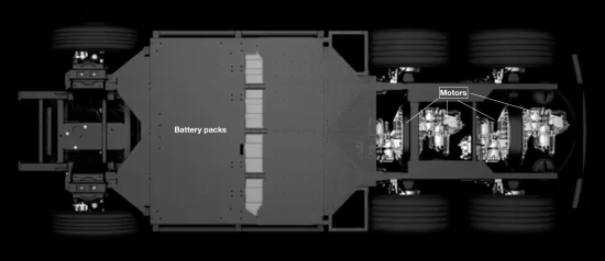
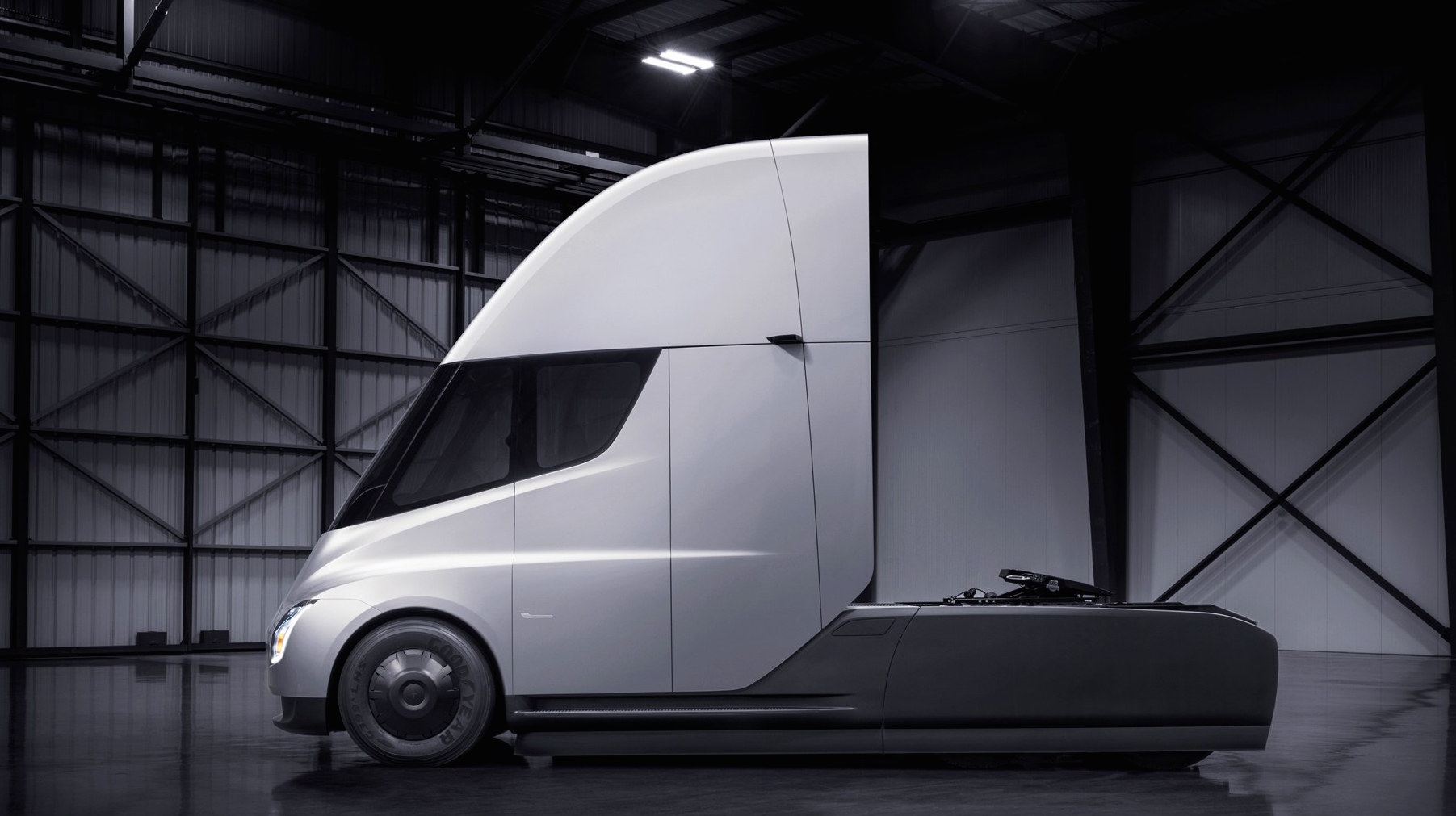
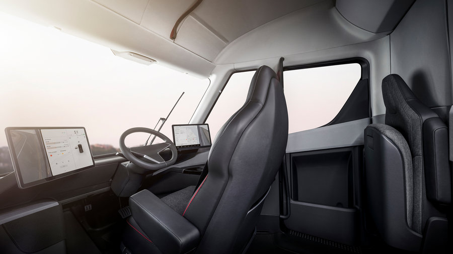
Tesla Truck prototype development

Design Contributions
- Pneumatic System - Air Compressor and Distribution
- Power Steering System
- Custom motor design, machining, fabrication
- Rotary mechanics & power transfer
- High-voltage system
- Low-voltage architecture & harnessing
- Firmware development & validation
Completed November 2017
Photos

Van Conversion interior & ancillary power system
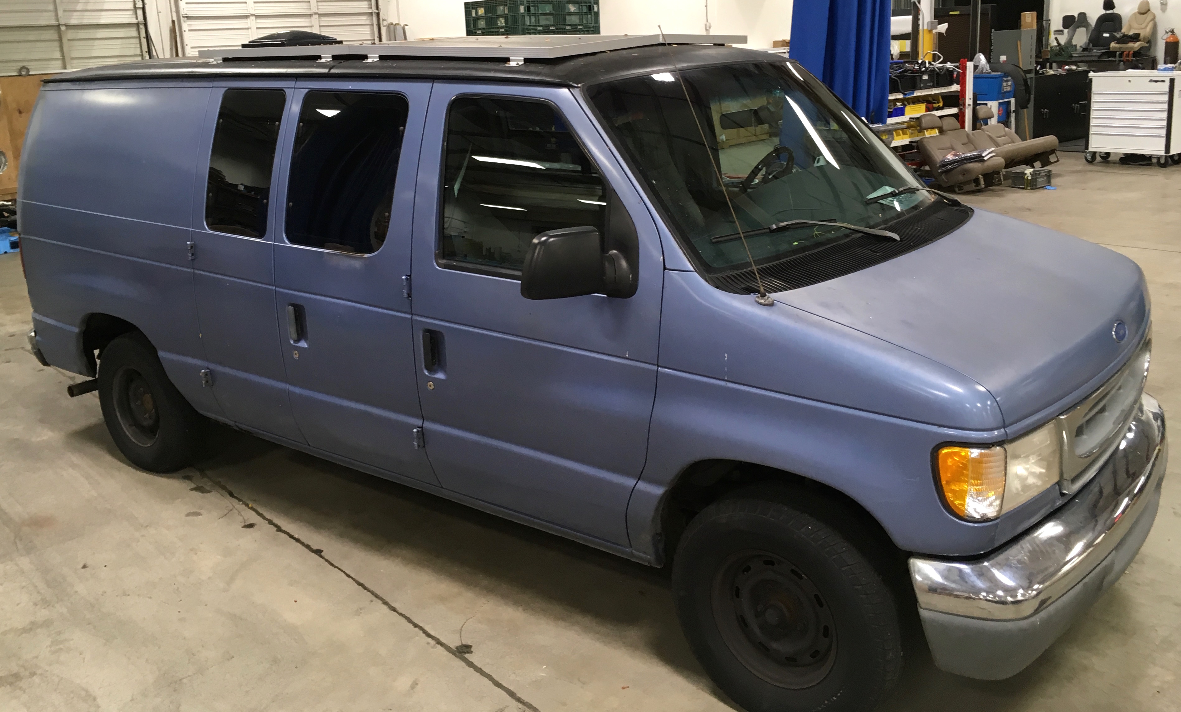
Project Description
- Rust removal, fiberglass repair, vent installation.
- Interior removal & re-construction
- R12 Thermal Insulation & Vapor Barrier
- Wiring for 12VDC & 120VAC
- Low-profile solar kit, integrated charge controller
- 3kWh Li-Ion Battery
- Window-tint & privacy blinds
Completed May 2017
Photos
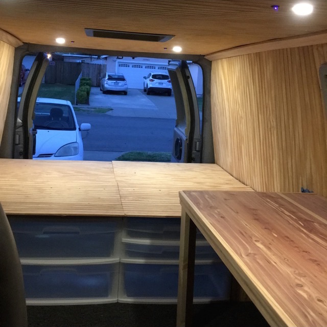
Wood panel interior with removobale, modular furniture.

Solar charge controoler installed in interior wall.
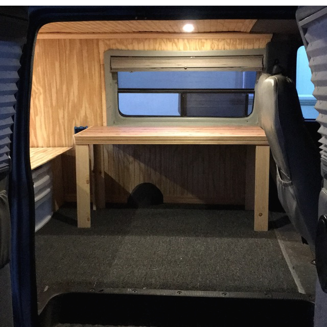
Interior with desk and window with blinds.
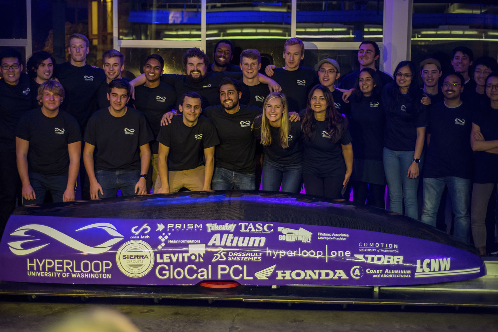
UW Hyperlooop director & electronics lead
- First annual SpaceX Hyperloop Competition
- Led team to place in global top 10
- Managed project with $20k budget and 30+ students
- High-voltage power system design and build
- Low-Voltage and control architecture
- Low-voltage architecture, harnessing and integration
- Chassis and composite fairing manufacture
Jan 2016 - Feb 2017
Photos
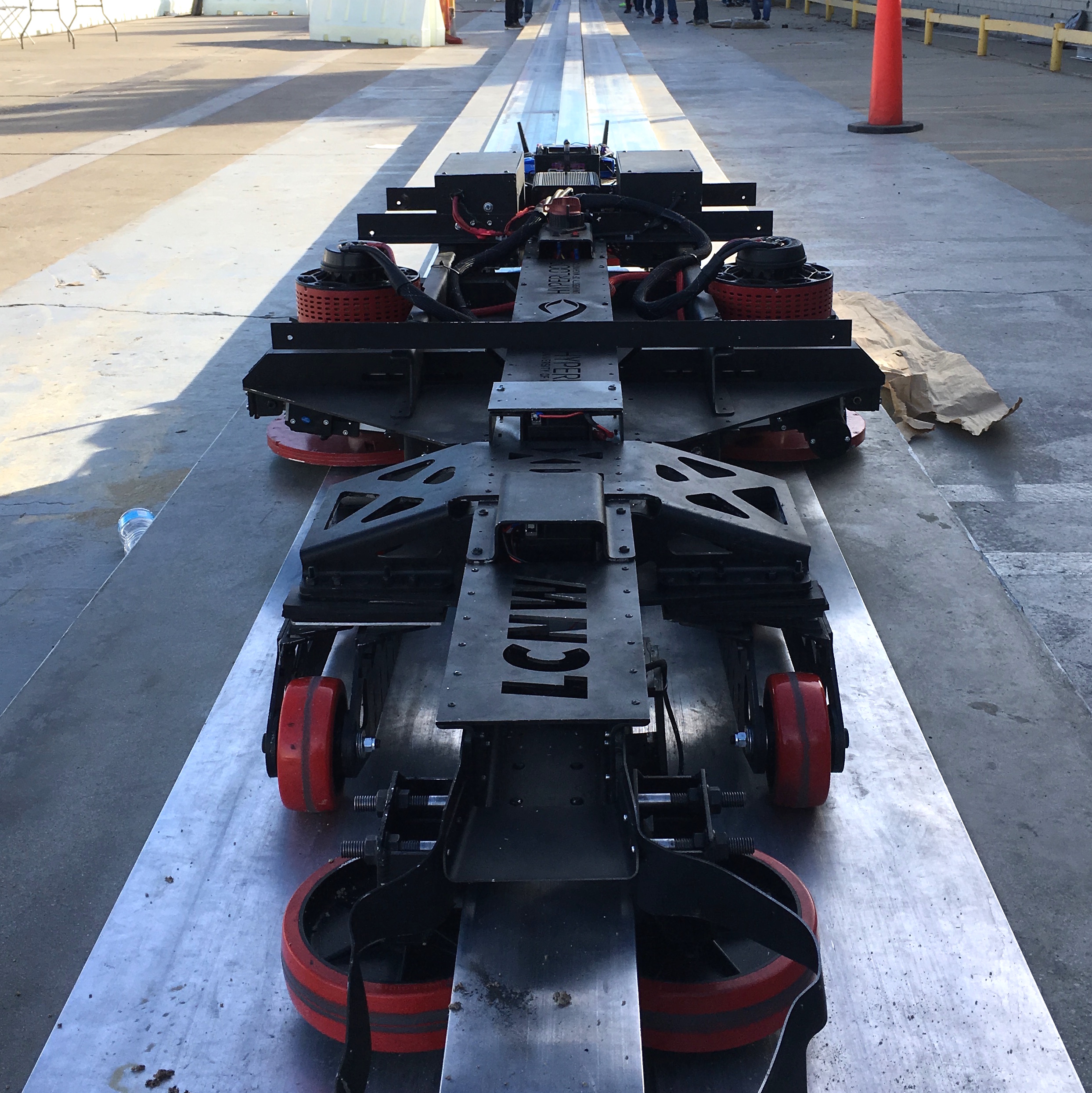
Pod being tested during competition weekend.
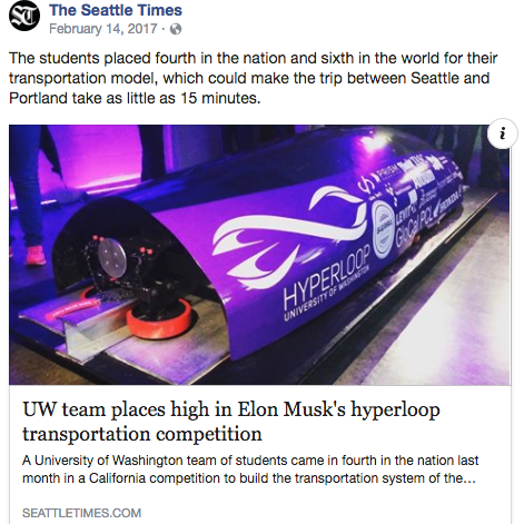
The Seattle Times article on the team's sucess at SpaceX.
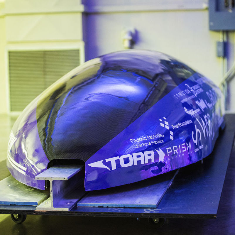
Profile view of the pod at the pre-competition reveal event.
Lithium Battery System design and construction
Description
To power a pair of 20kW Saietta 95-R DC motors, I designed, built and tested a complete lithium battery system consisting of two 12-cell, 48V lithium packs. Each pack contains 12 BlueEnergy EH5 5Ah cells. Connected in series, these packs utilize Linear Technology's state of the art LTC6804 multicell monitor and LTC3300 balancer. These chips communicate via SPI on a demo board, updating and balancing the cell voltages.
I added AllCell PCC48 cooling wax to the battery packs along the outside edges of the cells. The wax is designed to absorb ~1.6kJ of thermal energy, to keep the batteries within their safe operating range throughout a complete discharge cycle in a vacuum. In the event that the batteries overheat, integrated thermistors allow monitoring of the cell's temperature for emergency shutdown.
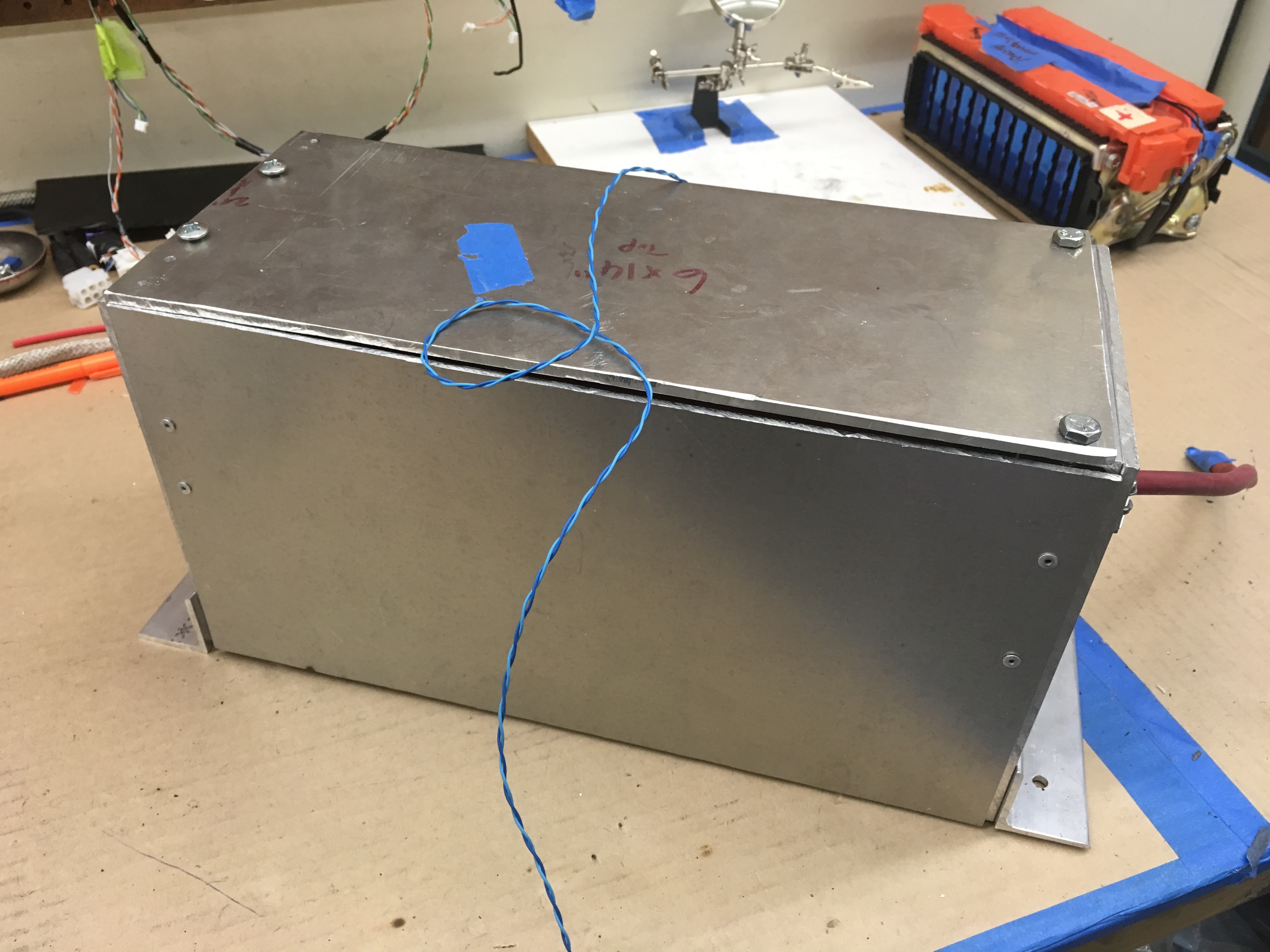
To mitigate fire and protect the batteries, I designed and built a 0.125" 6061-T6 enclosure to house both the pack, and the management PCB in a streamlined package.
Features
- 0.125" 6061 T6 Aluminum Enclosure w/ Partition
- Linear Technology DC2100B Battery Manager & Balancing board
- Integrated temperature sensors
- Ports for easy connection via USB and RJ45
- Top & bottom access panels
- AllCell cooling wax for increased thermal capacity
- 4AWG connectors for loads exceeding 200A
Completed January 2017
Images
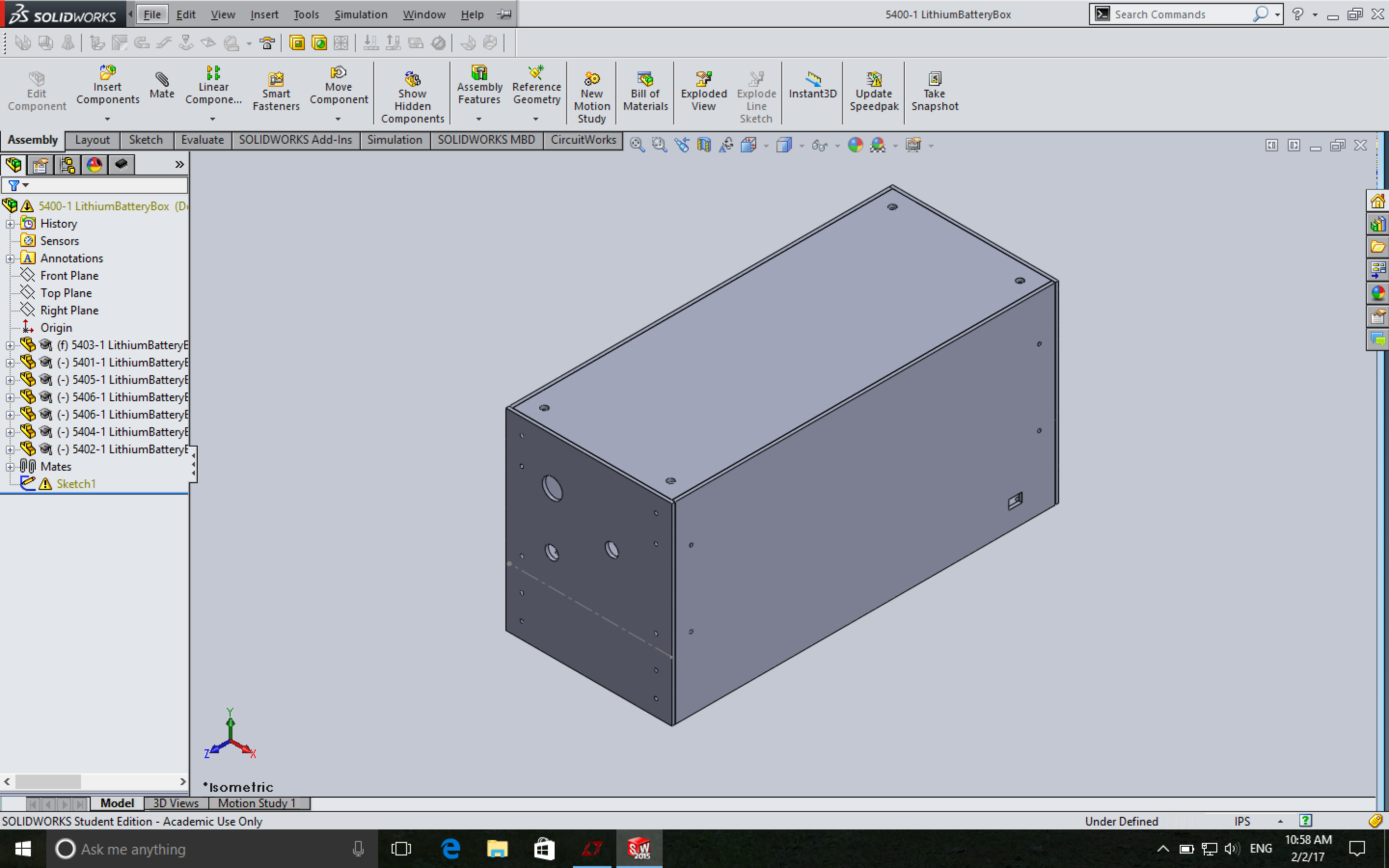
Solidworks assembly of the battery box. After creating the assembly to make sure that the fitment was correct, I made drawings and had the pieces laser cut.
A first prototype of the system, rough cut by hand to verify that the spatial geometry.
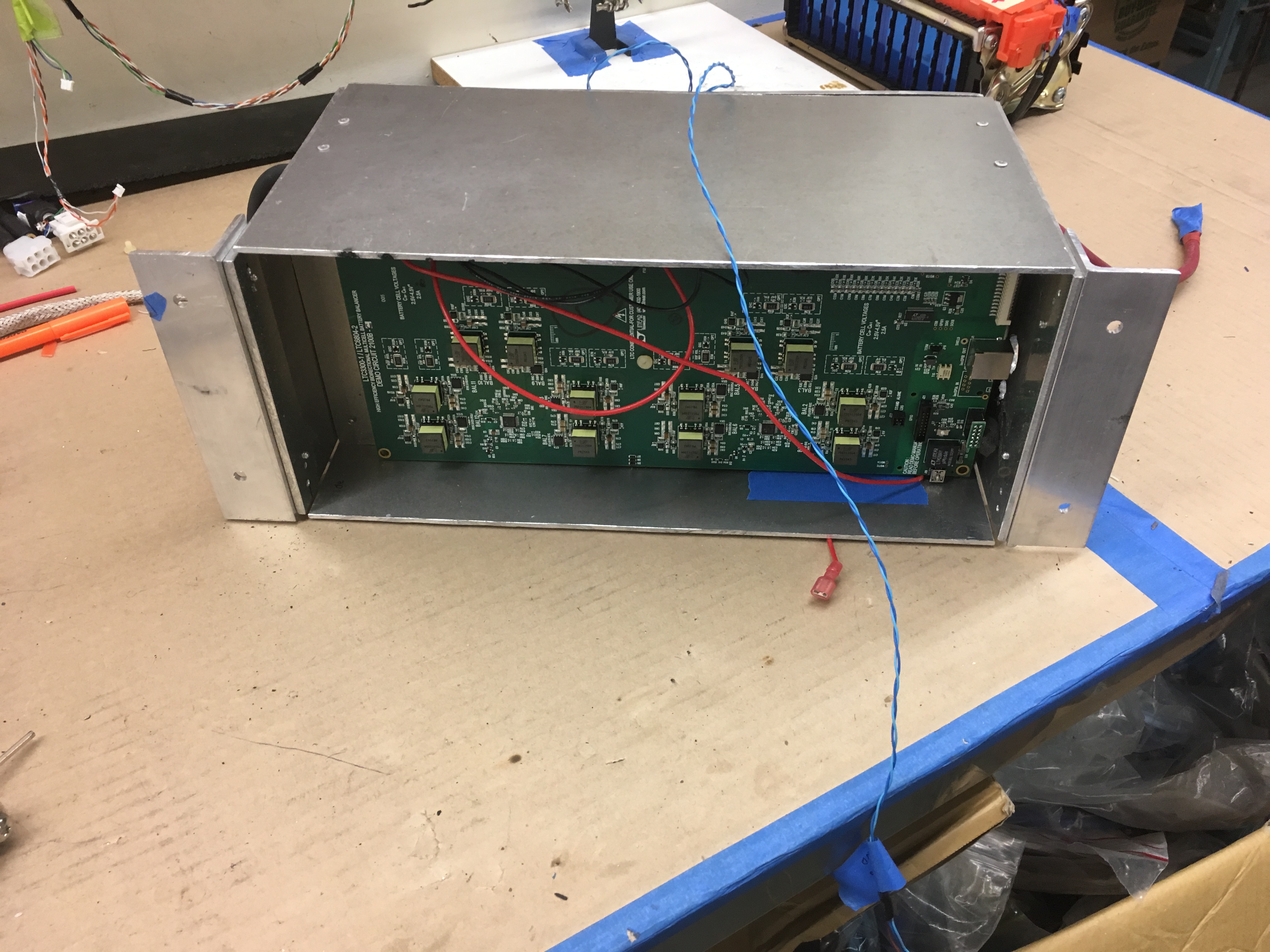
Manager board in the first prototype, where the need for standoffs and flipping the PCB became apparent.
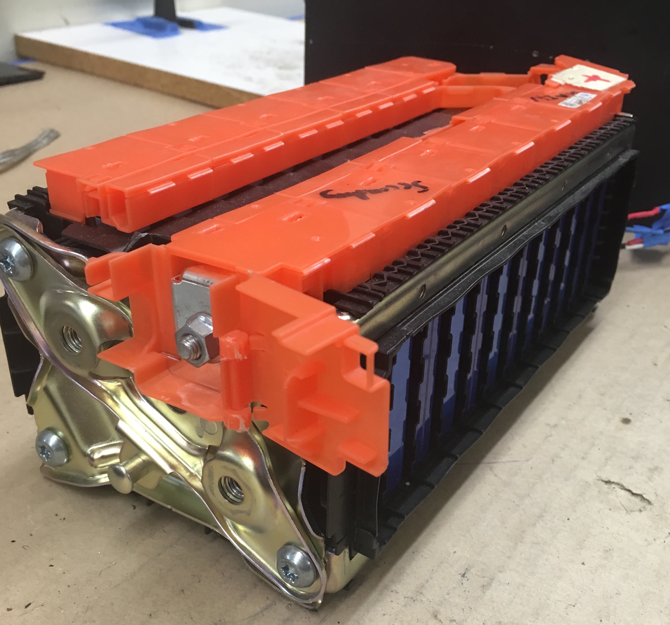
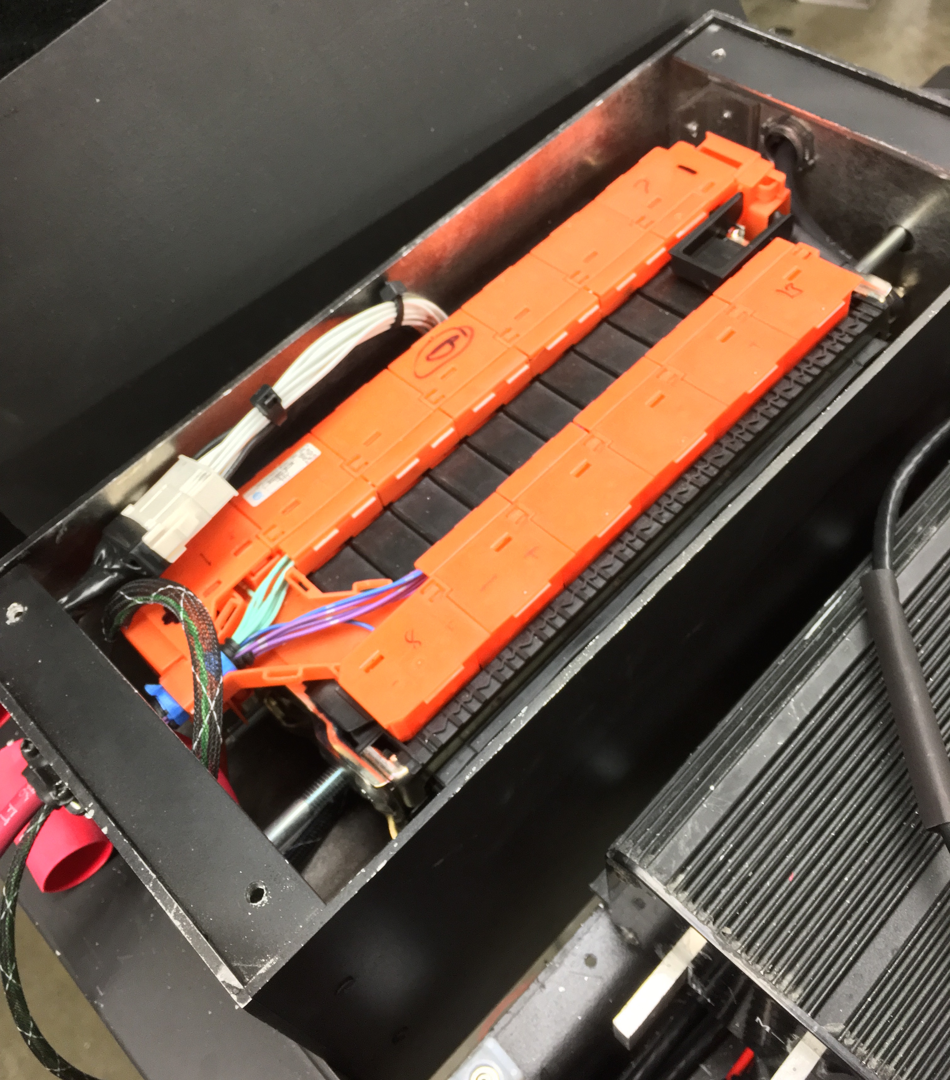
The battery pack, before cooling wax installation.
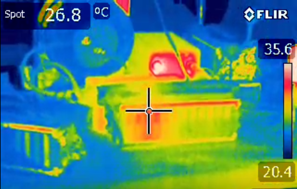
Thermal image of the battery pack during a high-current test to verify correct thermal analysis and wax specification.
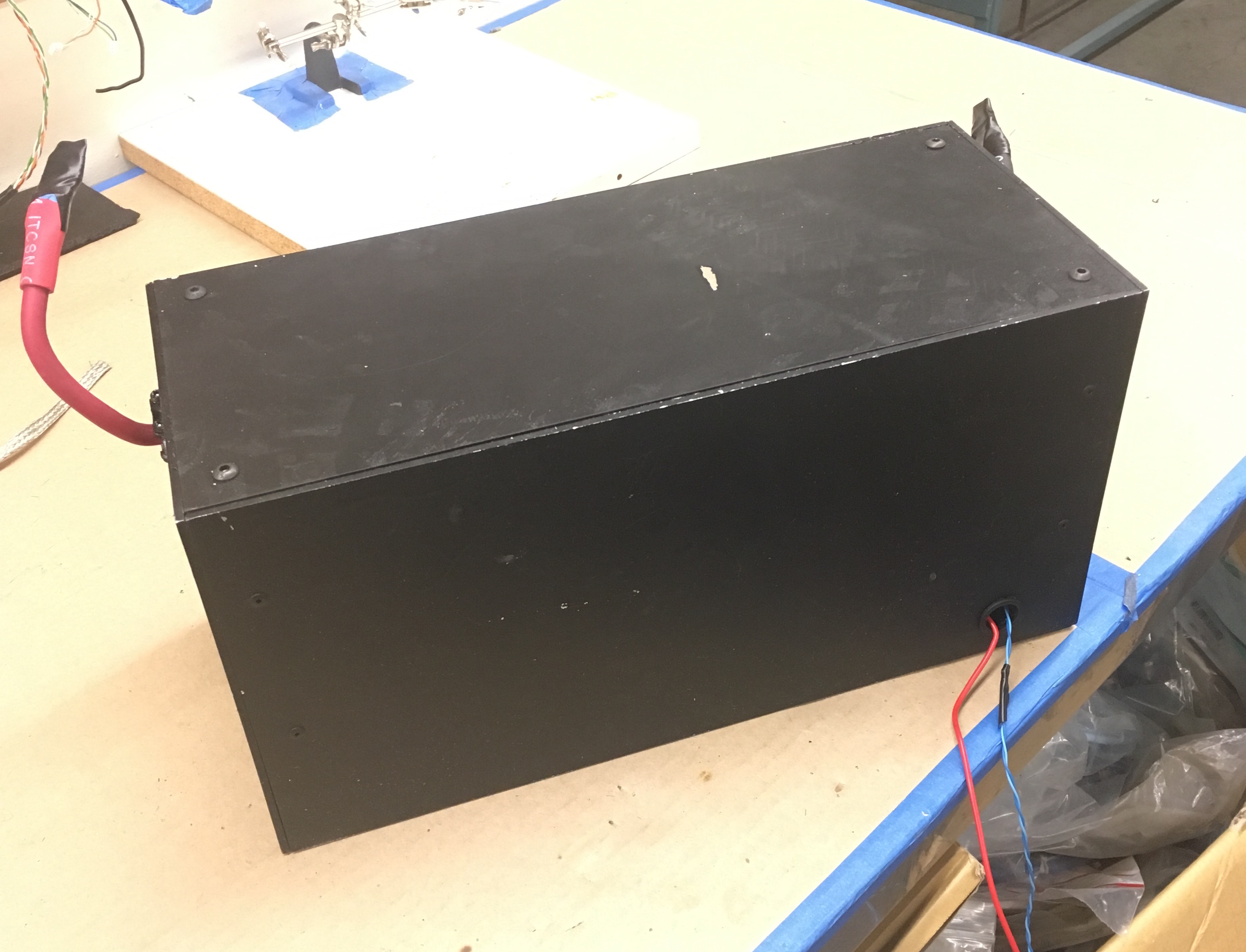
Profile view of the completed system, 1 of 4 total made.
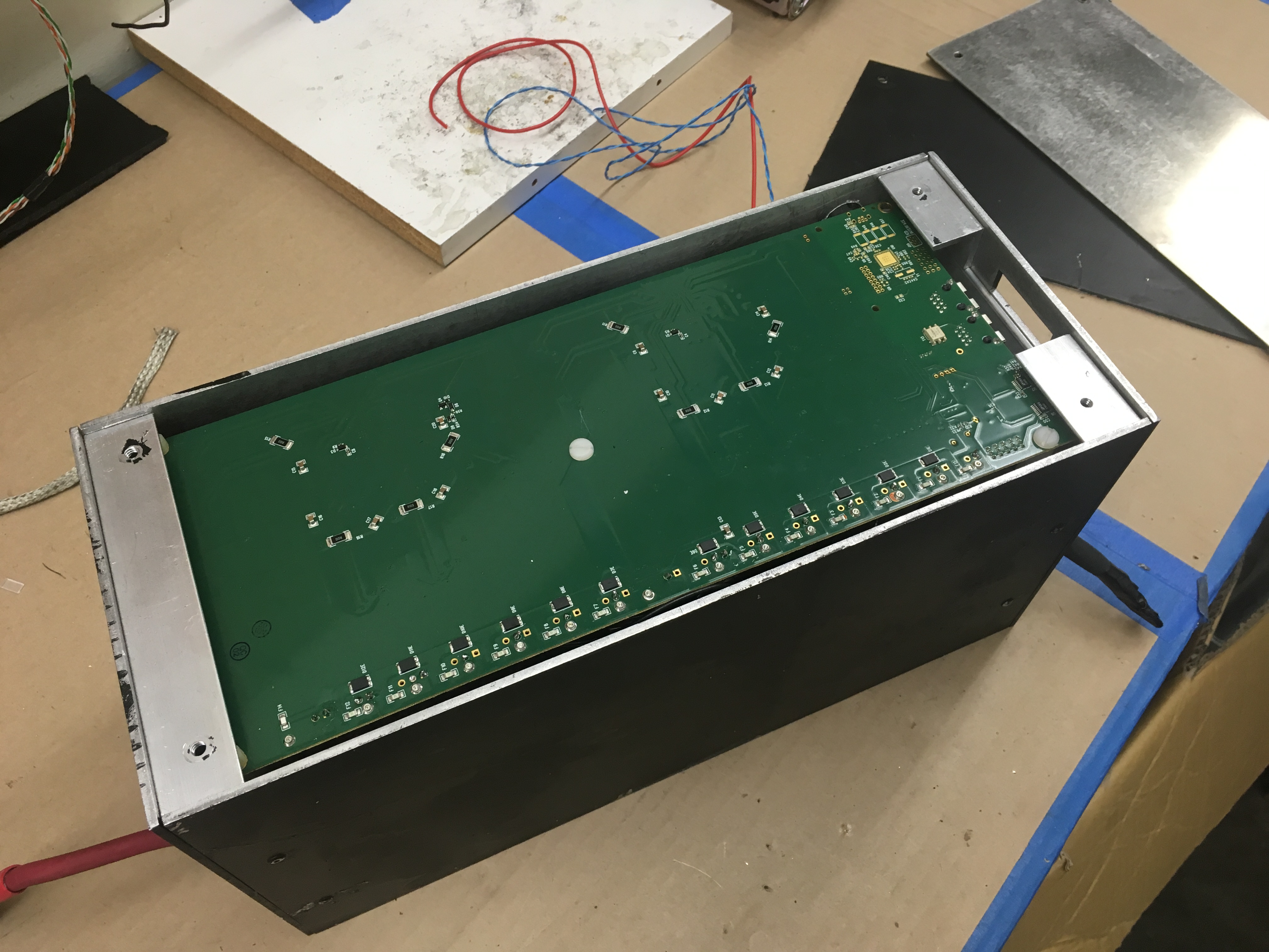
Final configuration of management PCB, mounted with standoffs for easy access and troubleshooting.
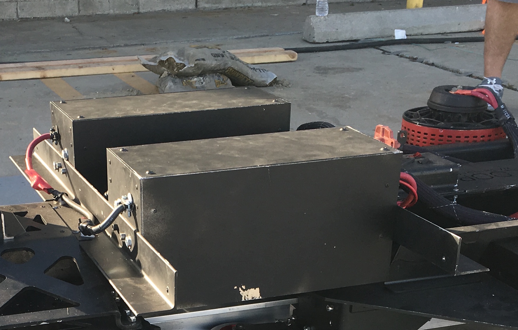
The final product, installed onto the Hyperloop pod for high-speed use.
Electromagnetic Propulsion System dynamic thrust using eddy currents
Description
To provide propulsion to our Hyperloop pod at speeds up to 150m/s, we constructed a simple and innately elegant solution. The system consists of two main components, a DC motor and a rotor. The rotor generates eddy currents in the aluminum track, which produce drag propelling the pod forward. The configuration and alignment of the rotor is proprietary and in optimized form generates around 65N of thrust per rotor. The beauty here is that this thrust is generated with no contact forces and grips at any speed, regardless of the weight of the pod.
Components
- 100V Honda Lithium Battery Pack
- Kelly KDH12010E Controller
- Saietta 95-R DC Motor
- LoveJoy Shaft Couplers
- Pillow-Block Bearings
- 12" Halbach Rotor
Completed December 2016
Photos
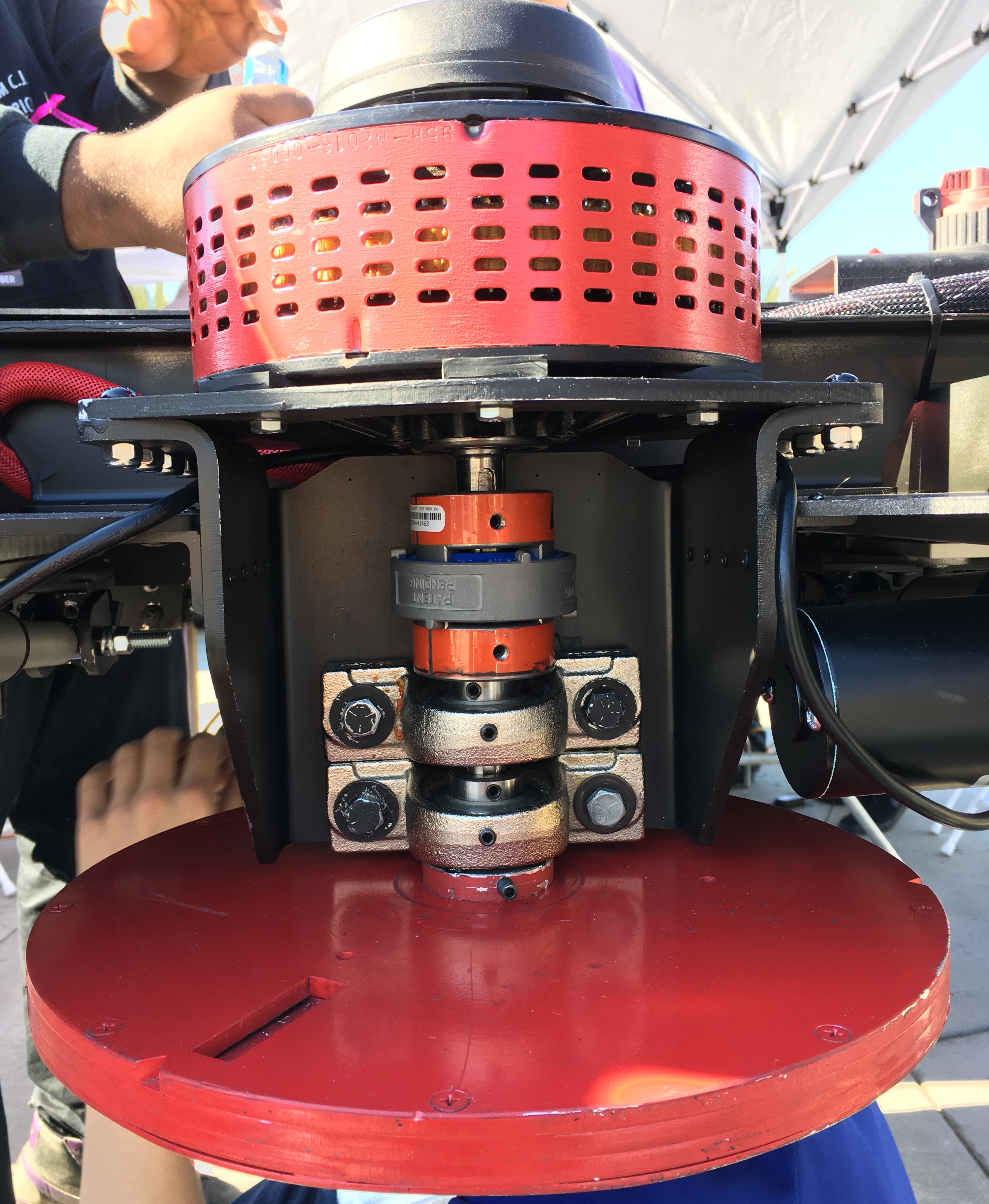
From top to bottom: motor, shaft coupler, pillow block bearings and magnetic rotor assembly.
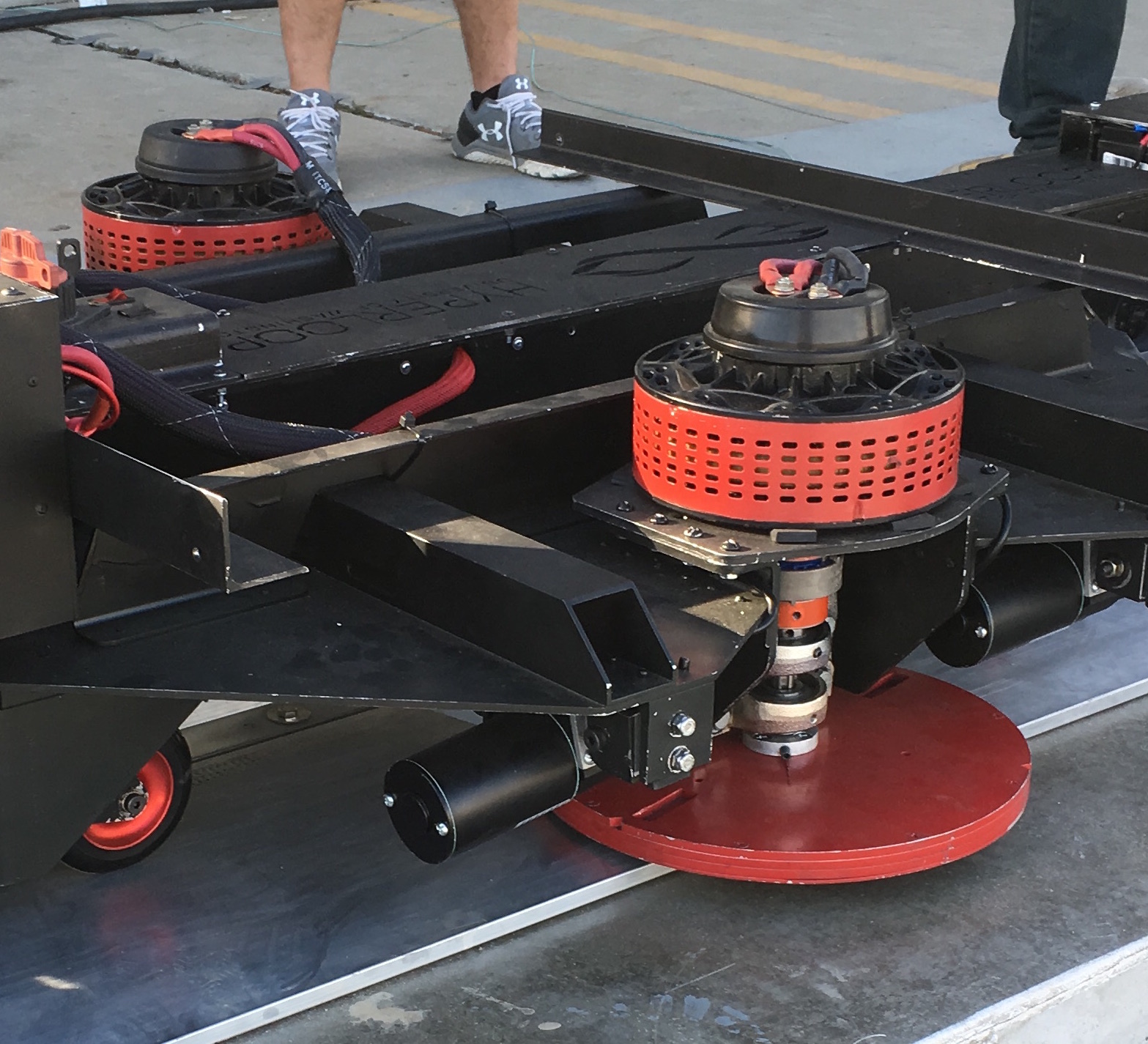
Macro display of the system integrated into the Pod's 'bogey' or propulsion/braking mechanism.
Carbon Fiber Fairing tooling, layup and finishing
Description
Constructing a carbon fiber fairing to envelop our Hyperloop pod, we rushed to produce an aesthetically pleasing layup in the weeks leading up to our unveiling and competition. The first attempt turned out poorly, making us repair the mold before we could attempt the second successful layup. The 10,000 square-inch contour constitutes an impressive challenge for even the most experiences composite engineers. After 6 days of late nights in the lab, this is what we produced.
Process
- Cut and glue foam into halves of rough contour
- Mill relief of the fairing using 5-axis CNC
- Prime, mate and repair the two halves of milled mold
- Apply release agents to the primed mold
- Cut 2x2 carbon twill into overlapping layers
- Spread resin onto the dry fiber and lay sheets into the mold
- Seal impregnated layers and vacuum bag to fit the contour
- Gently remove shell, sanding, clear coating and polishing to finish
- Apply vinyl wrap with sponsor logos to finished fairing
Completed January 2017
Images
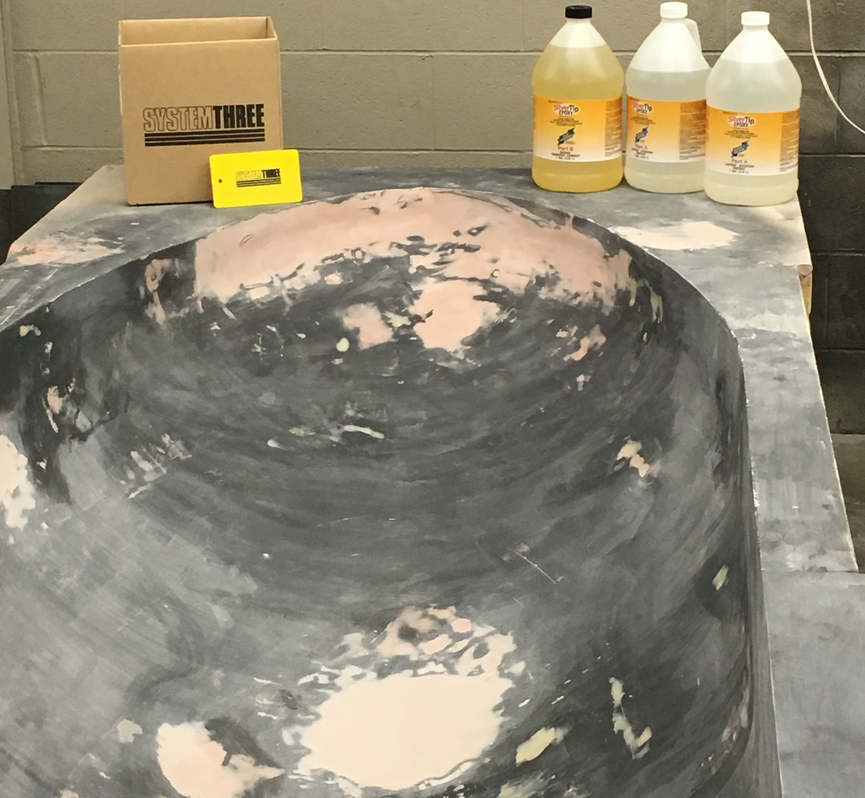
The repaired mold after the first, failed layup. Repairs were made with Bondo and clay to re-shape the contour of the shell.
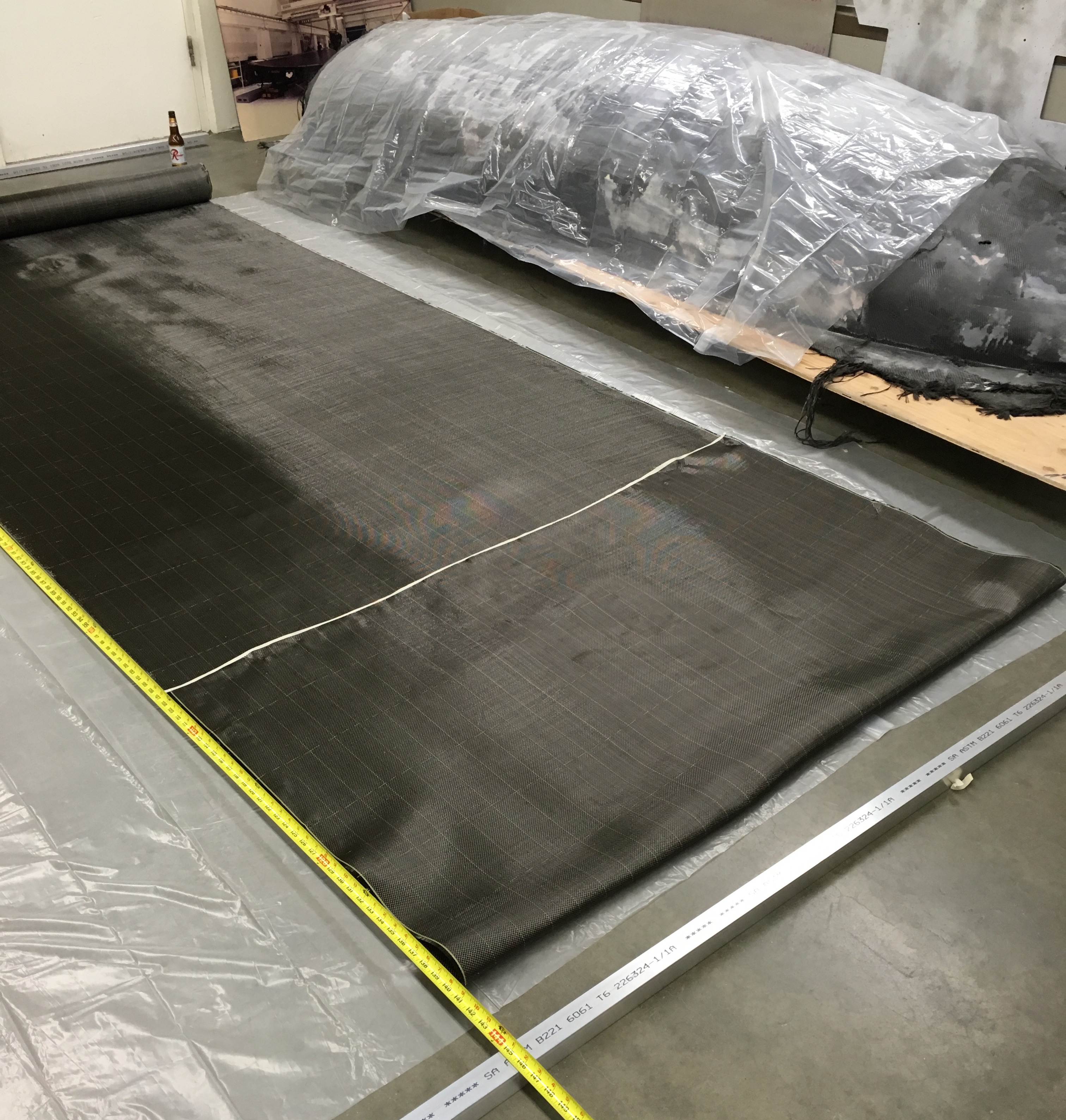
Carbon twill laid out next to the first, failed attempt as it is cut into specific layers.
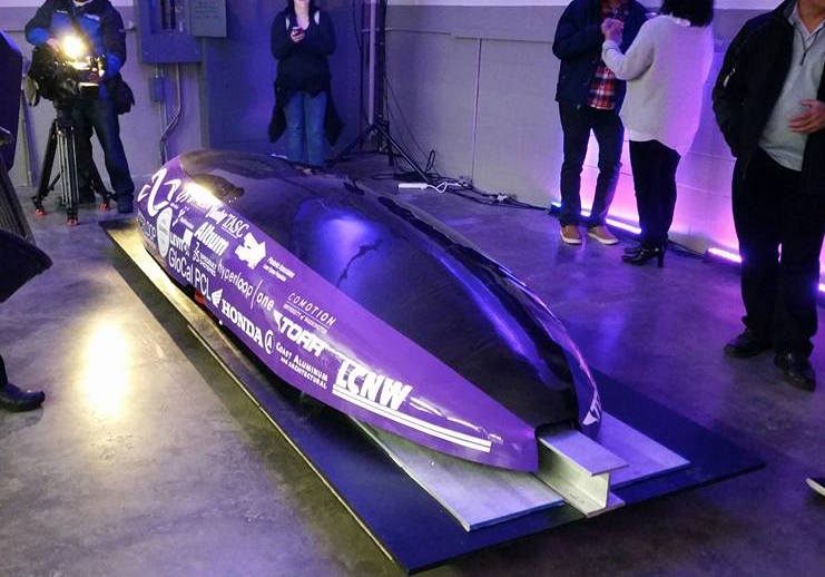
The final product, as seen by sponsors and news outlets during the unveiling event.
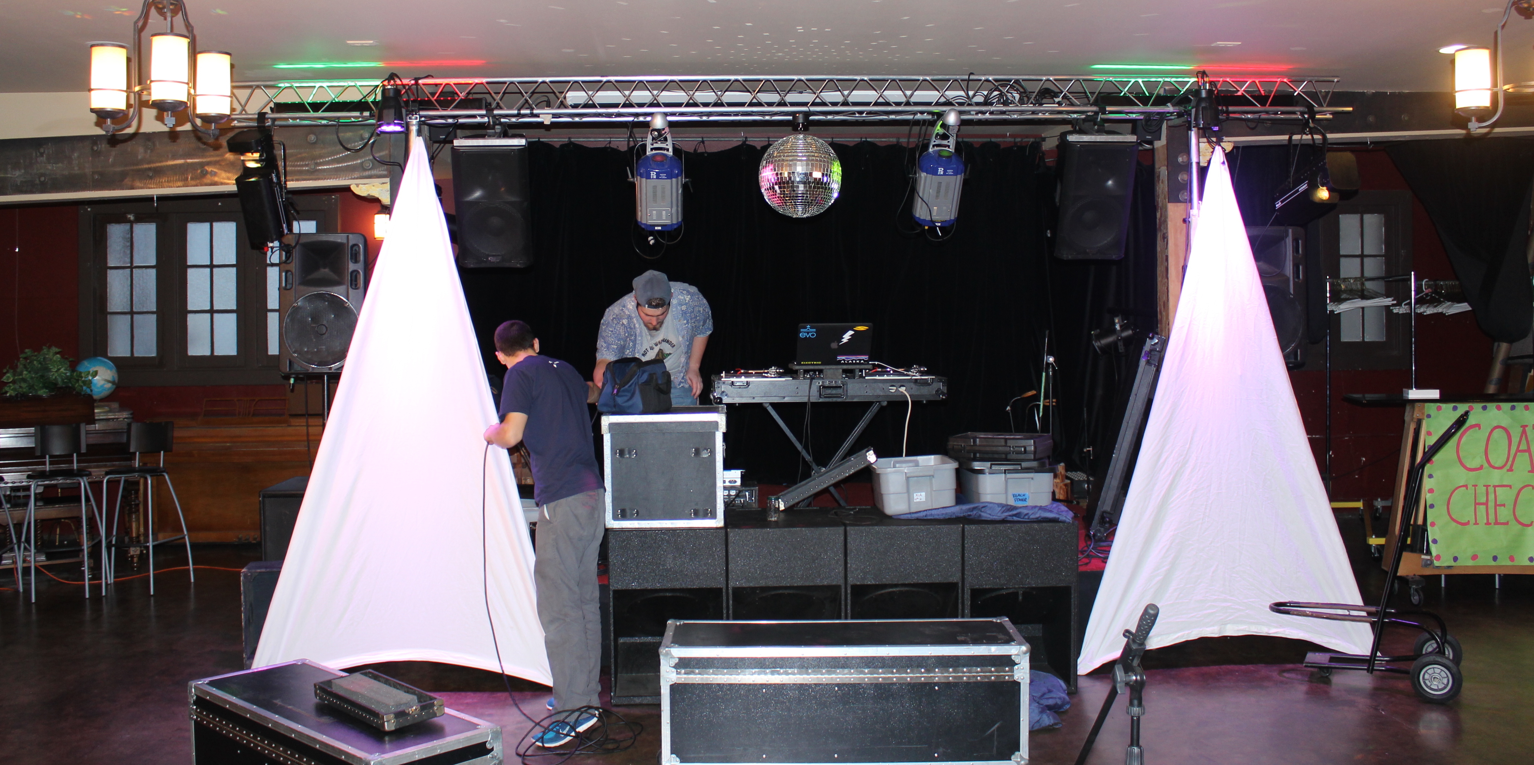
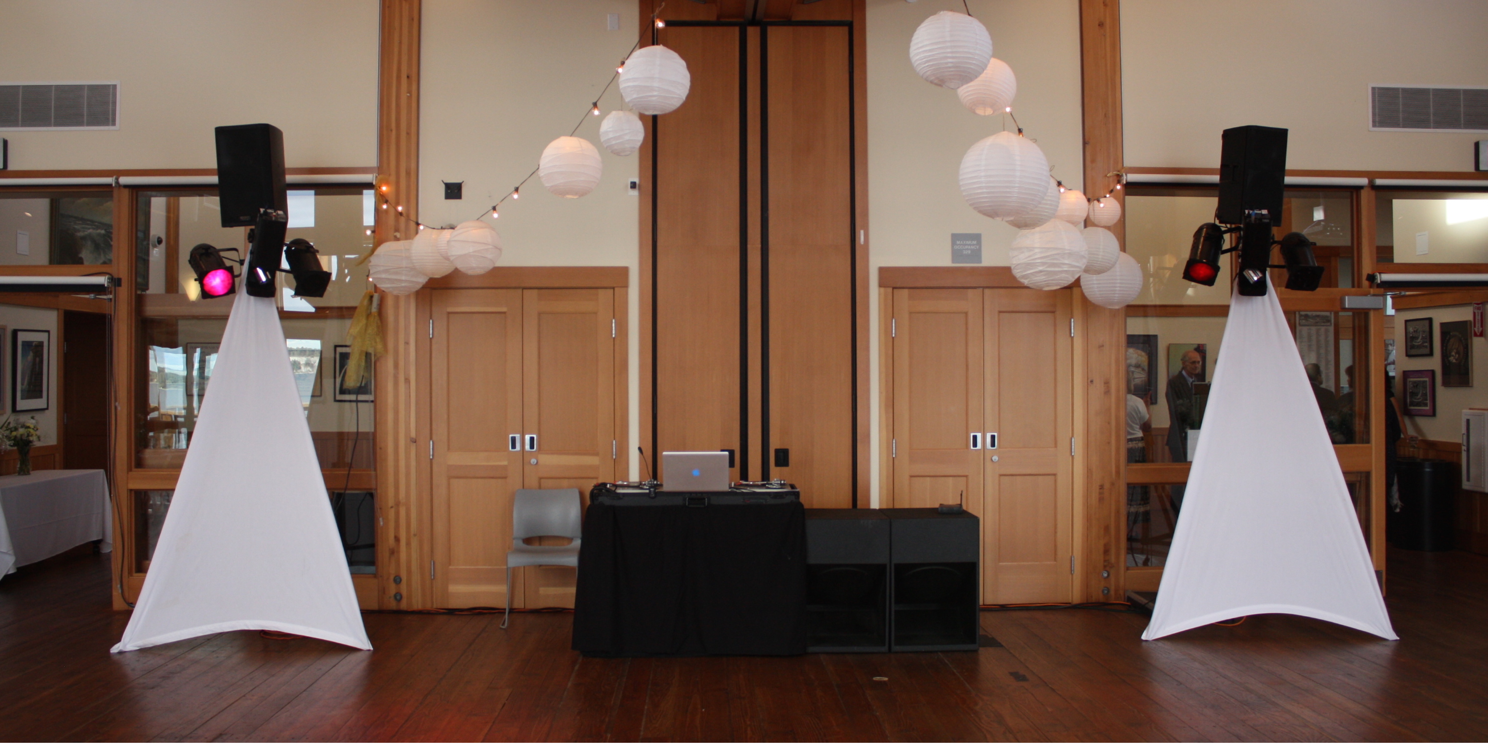
Memorable Music Event Services - DJ- Audio - Lighting
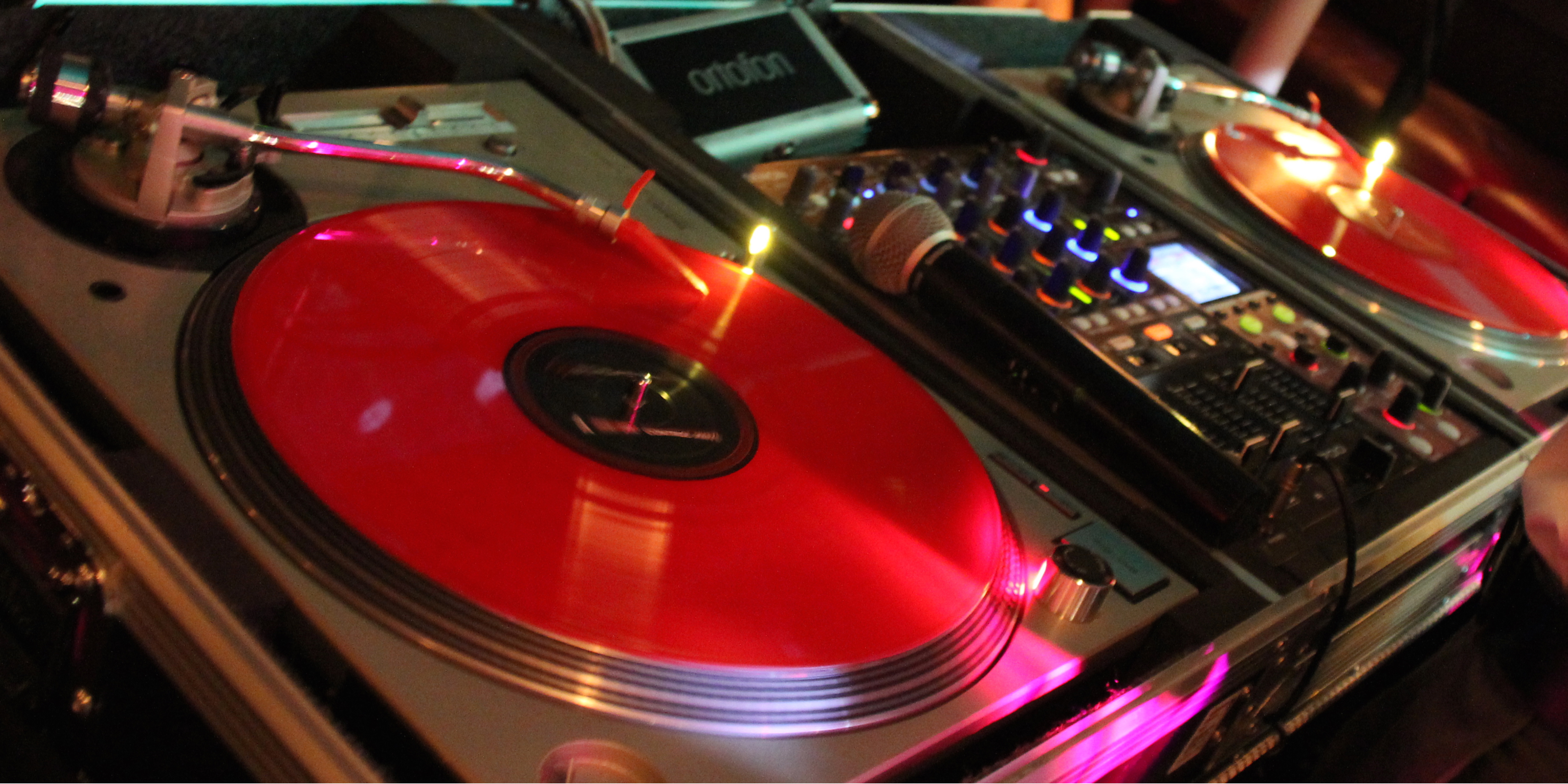
History
Founded when I was 13, Memorable Music serves to bridge my passions for audio and lighting with memories and joy at all kinds of unique events. The business operated as a hobby, offering professional DJ and event services at an afforable price.
Serices
- DJs for Weddings, Corporate Parties, Birthdays & More!
- AV system rental - 400+ person events
- Automated lighting system rentals
- AV equipment repair
2008 - 2017
More Photos
Cable Stress Test Fixture Controls design and construction
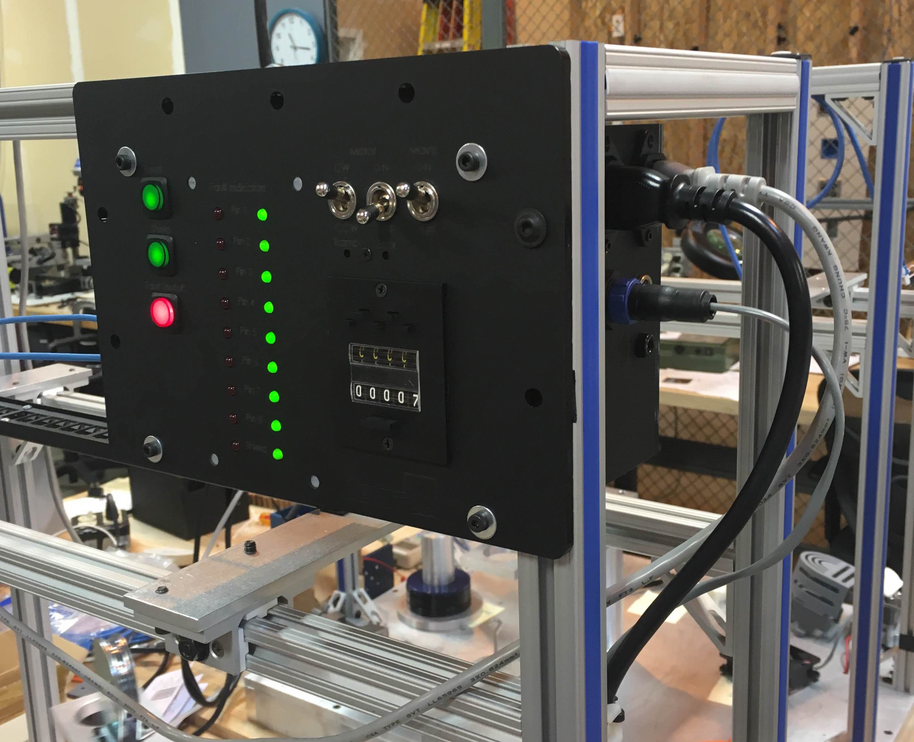
Description
In order to refine the quality control and certification process for twist-stress testing, I re-designed the control system for the rotating armature. My re-design included consolidating the electronics into a single enclosure, changing to operating voltage to a more standard, 12V while also adding a wide range of features including advanced fault detection and shutoff for intermittent cable faults on individual channels down to 2us interruptions.
Details
- Evaluation of design requirements from QA standards
- Performed trade study on improvement strategies
- CAD Design in Solidworks
- PCB design, testing and manufacture
- Electromechanical integration and assembly
Completed August 2016
More Photos
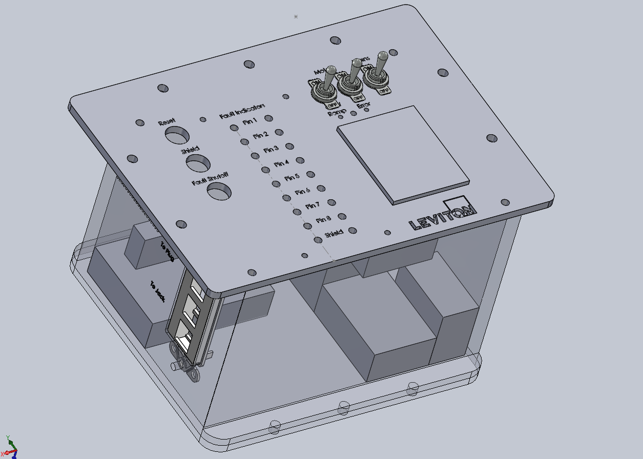
Solidworks assembly for custom enclosure.
PADS PCB design layout for printed circuit board.
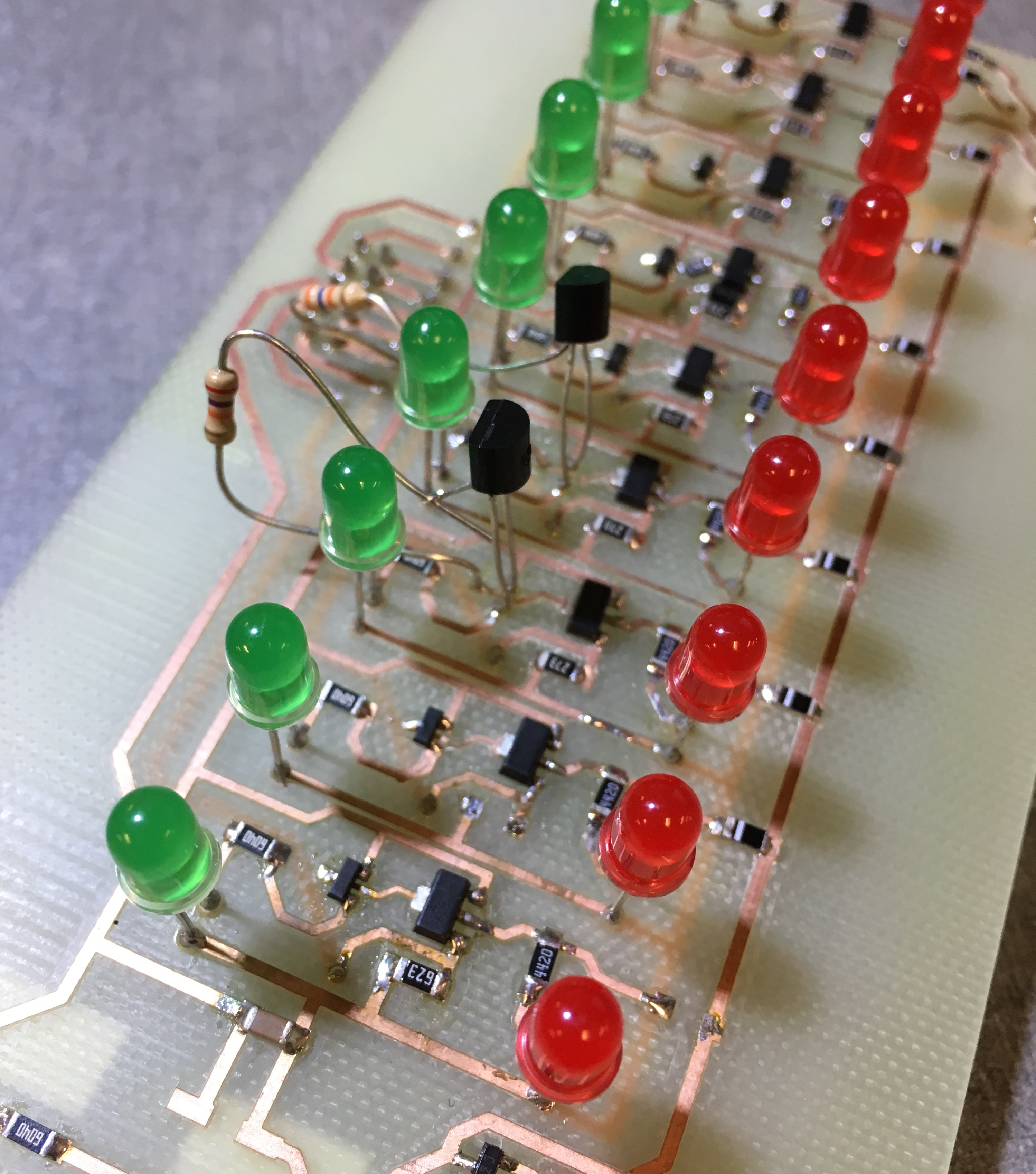
Prototype board with soldered components to optimize performance.
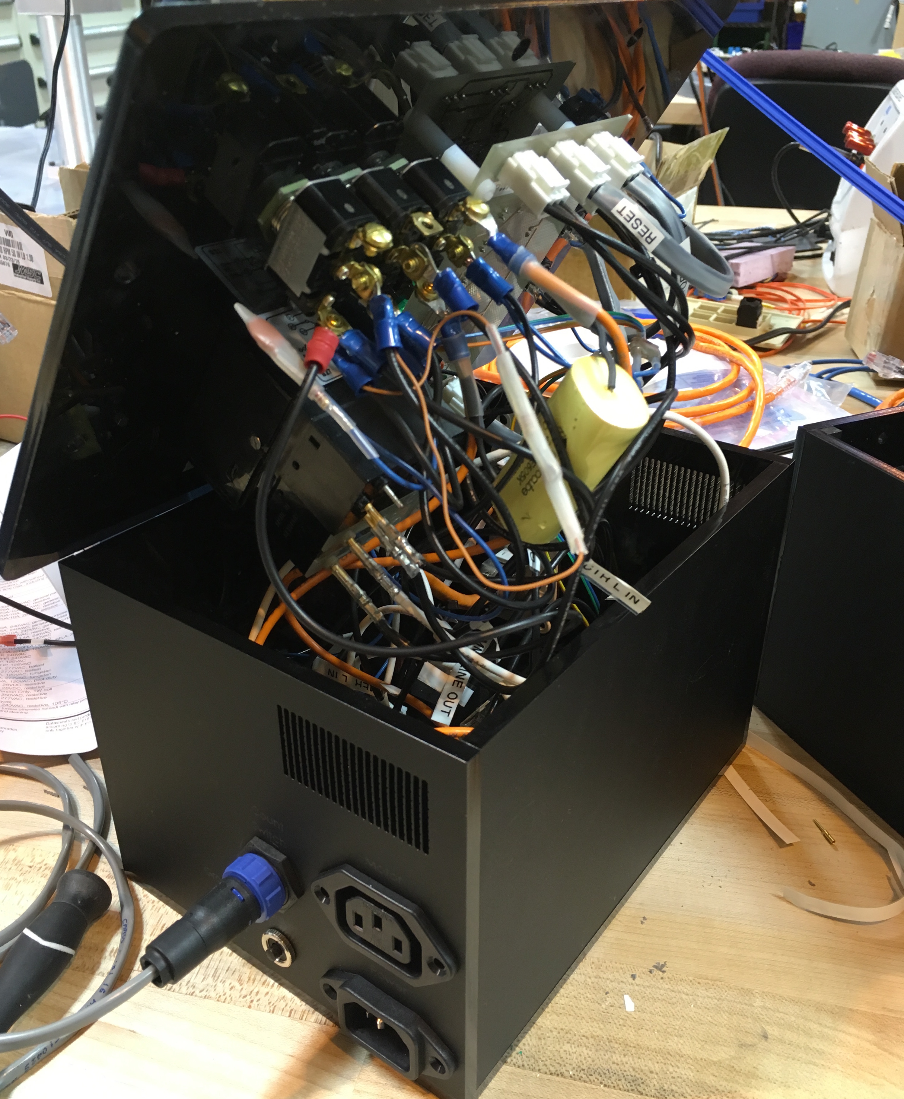
The insides of the fixture, wire managed and routed with dozens of connections.
PCB Design for PIC18F & CAN system development
Description
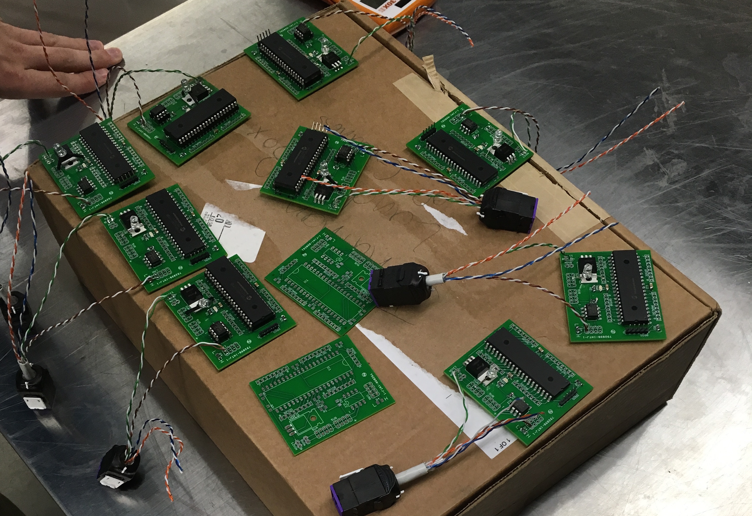
In order to construct a robust sensor and control system that connects a diverse range of sensors to a series of PIC microcontrollers communicating via a CAN network, I produced these simple printed PCBs. Designed using Eagle, the boards house the PIC, a CAN transceiver and a LM3904 Linear Regulator. Surrounding these components are filter capacitors, power and signal indication LEDs as well as GPIO headers for quick connection to hall effect sensors, IR optical distance sensors, thermistors, and more!
Completed September 2016
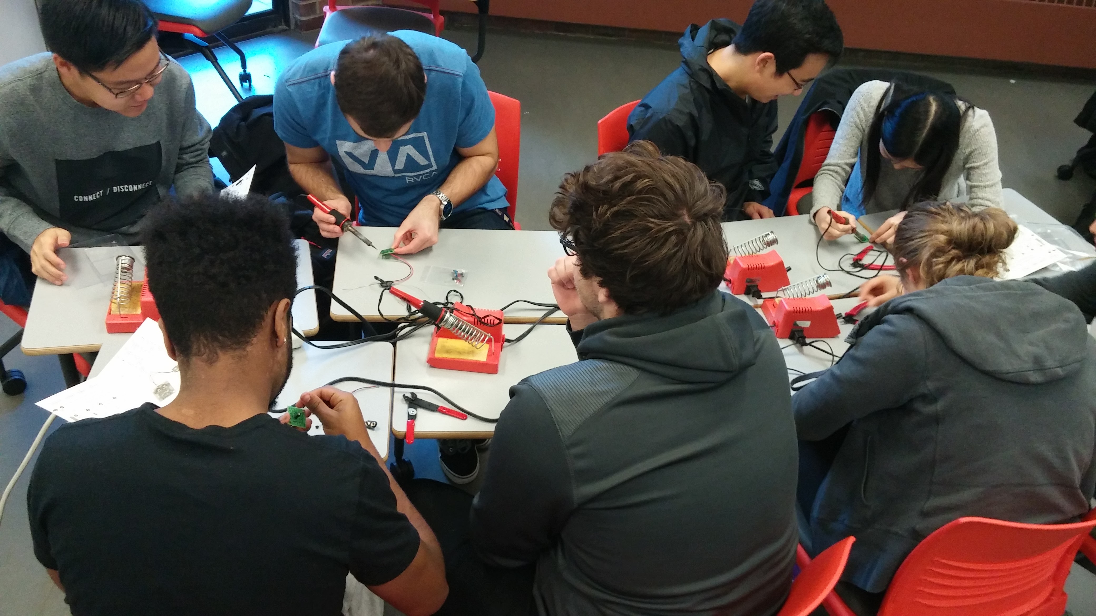
Soldering Workshop for University of Washington Electrical Engineering Freshman
Workshop Objectives
This workshop aimed to provide incoming EE's at the UW with some hands-on experience. Students gained insight into engineering by exploring the components that comprise a simple multivibrator circuit, learning how to solder and seeing it work! Having them work in groups allowed them to problem solve and develop more efficient methods to complete the project while also building community and communication skills. The circuit the students constructed can be found here: https://www.amazon.com/VELLEMAN-MK102-Flashing-LEDs-Kit/dp/B001VCMEVO
Learning Outcomes
- Teamwork and Communication
- Basic Circuit Theory
- Soldering
- Troubleshooting and de-bugging
December 2016
Photos
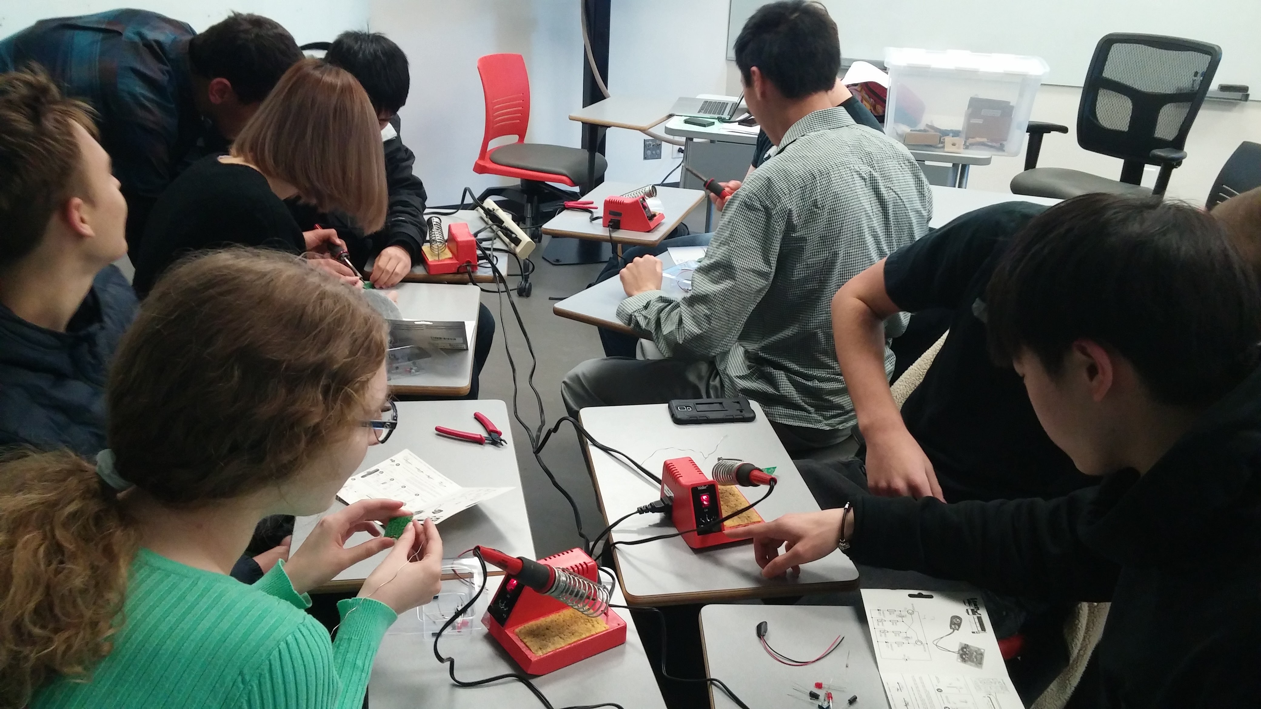
Students troubleshoot problems as they work through building the flasher circuit.

Completed Circuit!
Snake Game with an FPGA Digital Circuits
Description
A project for an embedded class, I decide to make the classic Snake arcade game on my Alterra FPGA. The game was constructed in SystemVerilog and controlled through the GPIOs of the Alterra De1 board. The 8x8 three color LED array and HEX displays present the state of the game while the buttons and switches on the side of the board provide the user interface.
Emphasized Skills
- Hardware Layout using Quartus
- Digital Circuit Design and Prototyping
- Periphery configuration and application
February 2016
Animation Stand design, prototyping and manufacturing for the Clay Animation Network
Description
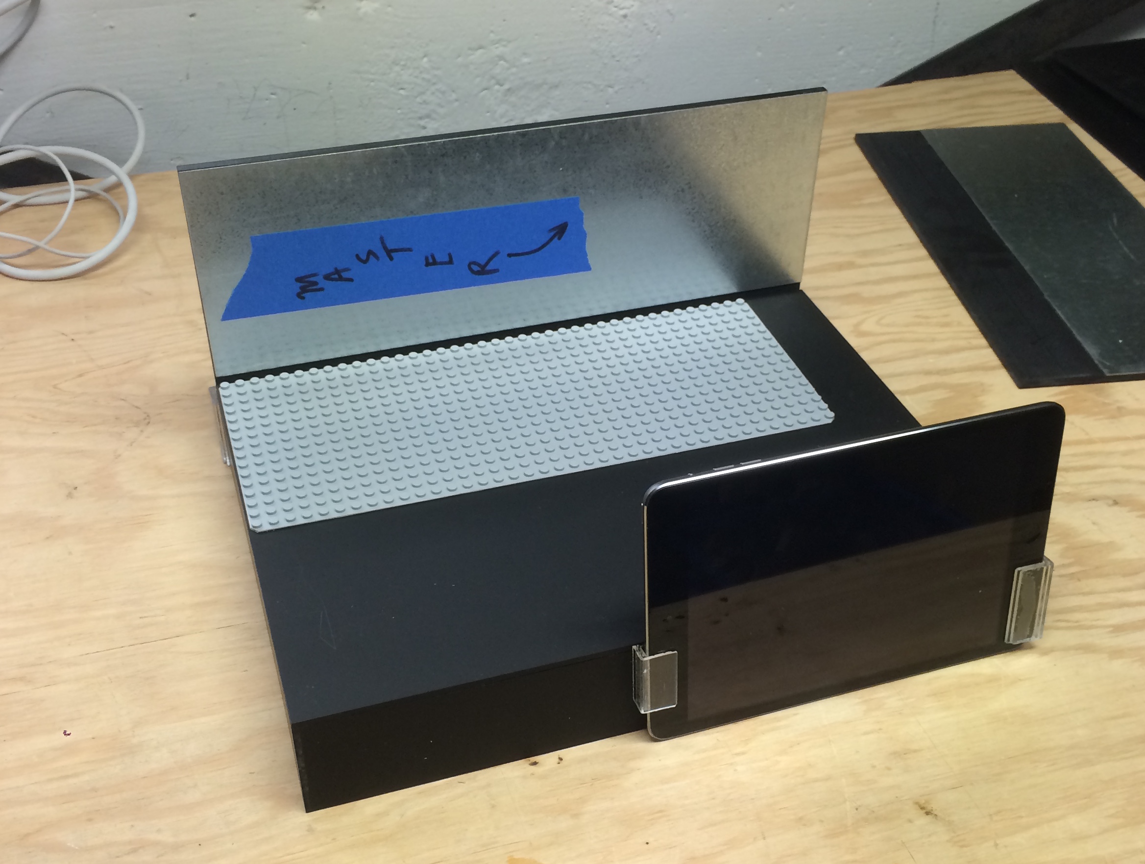
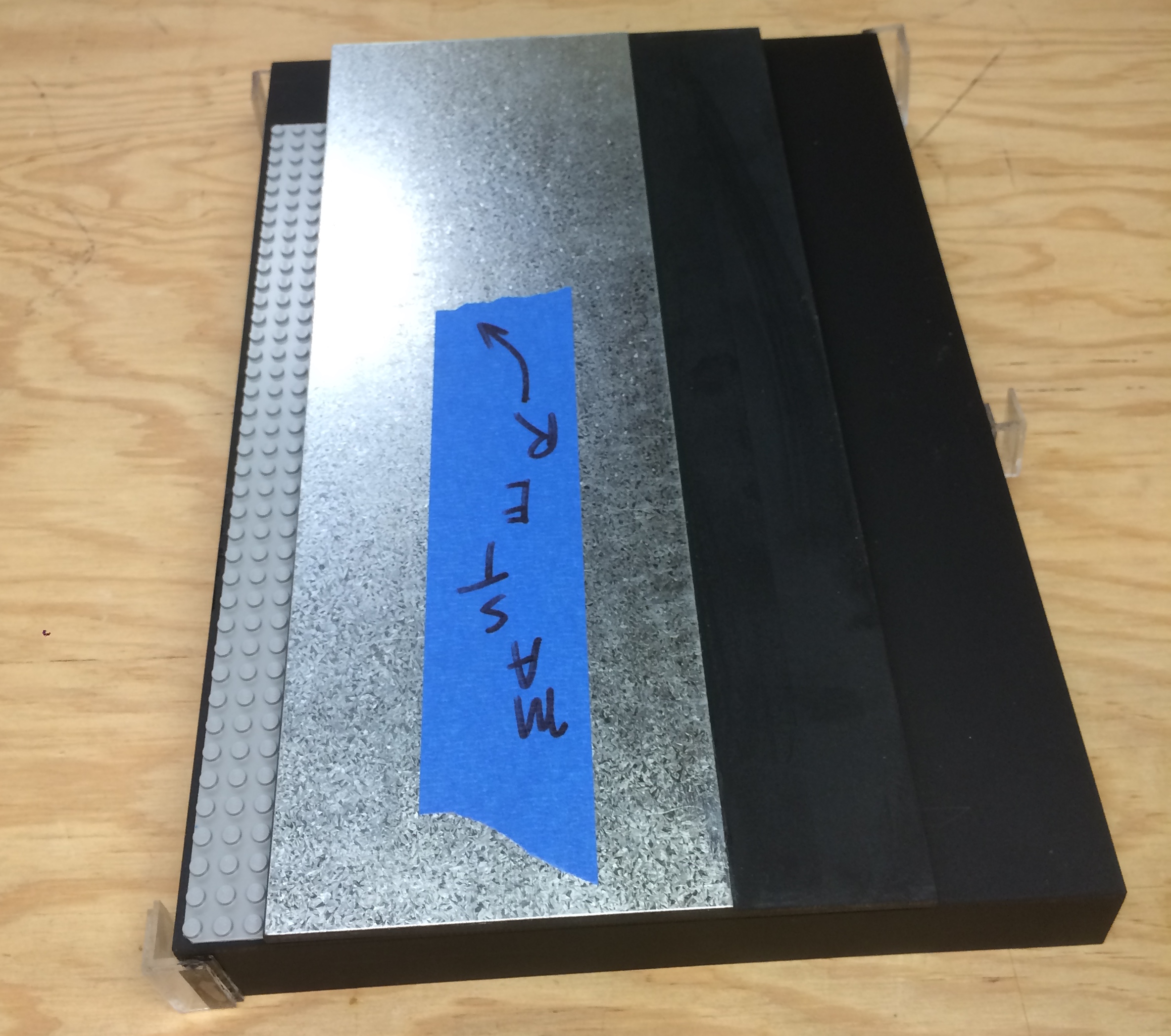
Over the course of 9 months I worked with Lukas Allenbaugh, Director of the Clay Animation Network, to produce a portable, lightweight, and durable Animation Stand for use in his mobile classes. Wanting a streamlined product designed for the iPad Mini and iStopMotion animation software I researched the optimal camera angle and distance from animating area to engineer ratios and dimensions for the stand. From there, materials and cost comparison determined that the stand should be made from Acrylic plastic. Following prototypes and design modifications the stand components were mass produced in my shop using customized jigs and routers. The photo on right provides an overview of the final product.
Project Details
- Research and Testing to guide product design
- Design using AutoCad
- Prototyping using tack-board and plastics
- Manufacture using custom jigs and routing and chemical adhesion
Completed August 2015
More Photos
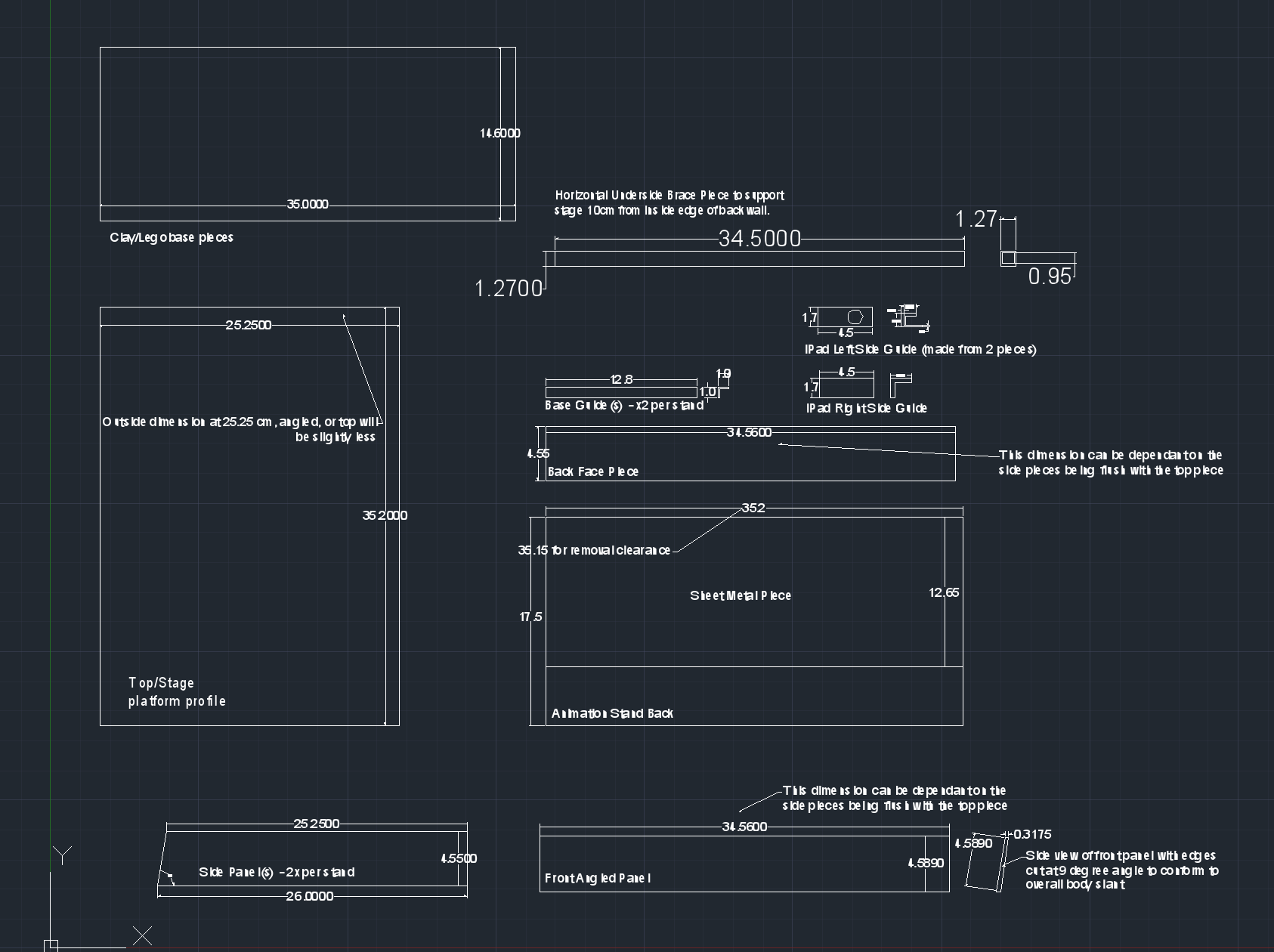
Overview of one of the CAD designs for the final product.
The Animation Stand easily comes apart and folds for transport and storage.
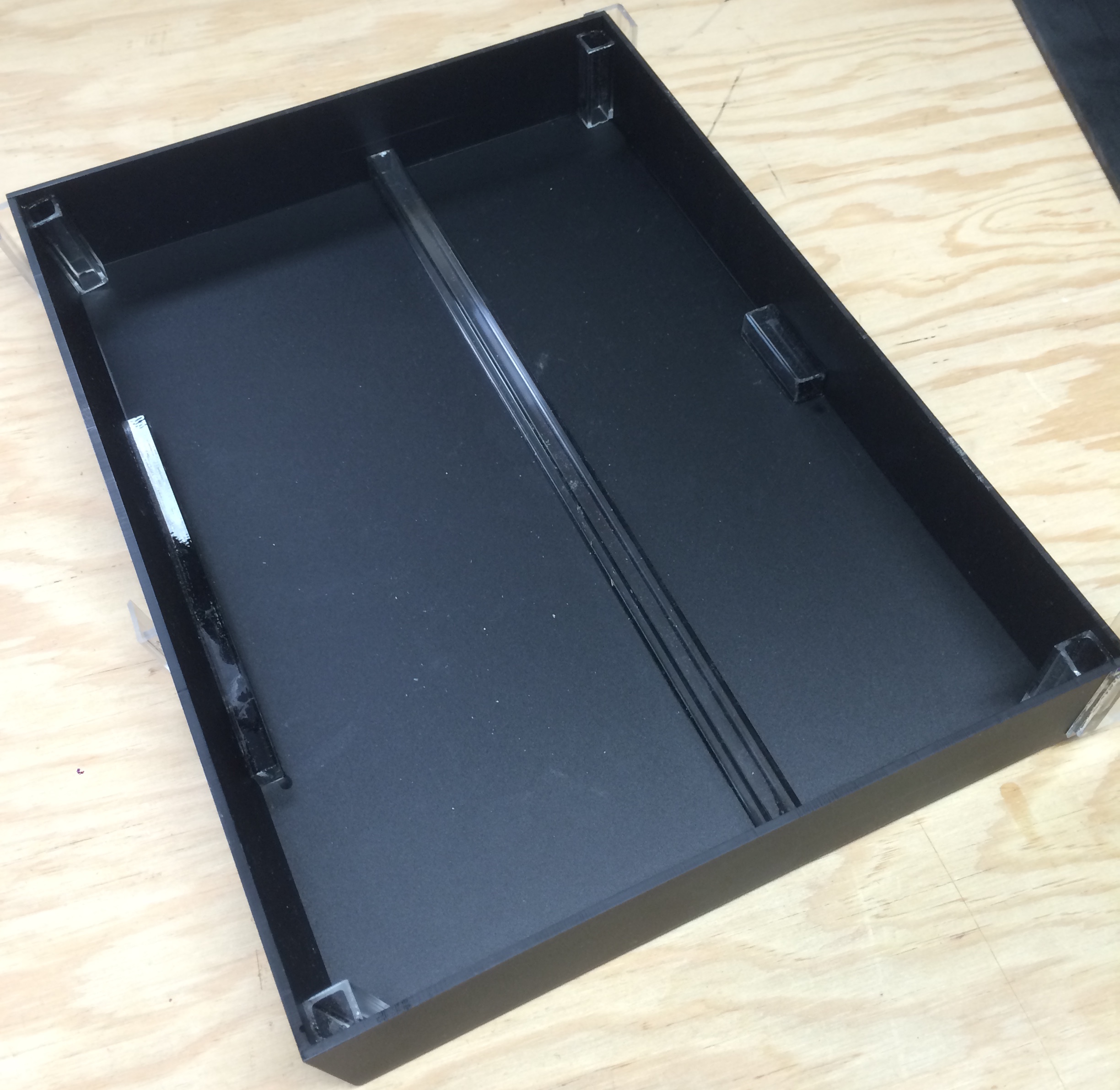
Underside of the Animation Stand, plastic reinforcements help to reduce flex while maintaining a lightweight body.
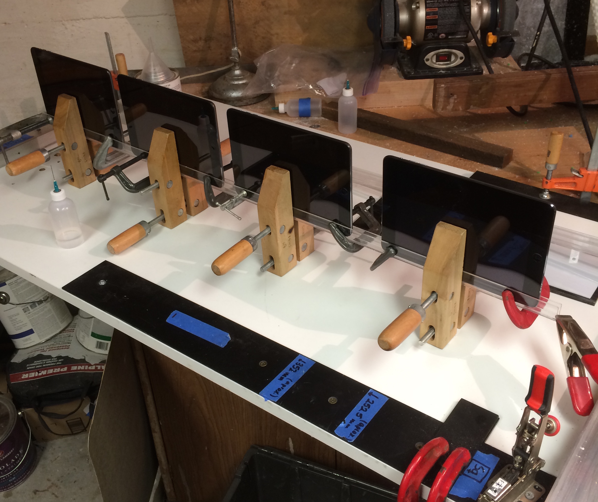
Creating the guides to hold the iPads to the stand body using clear Acrylic and clamps during adhesion.
Audio Mixer Circuit Design and Construction
Description
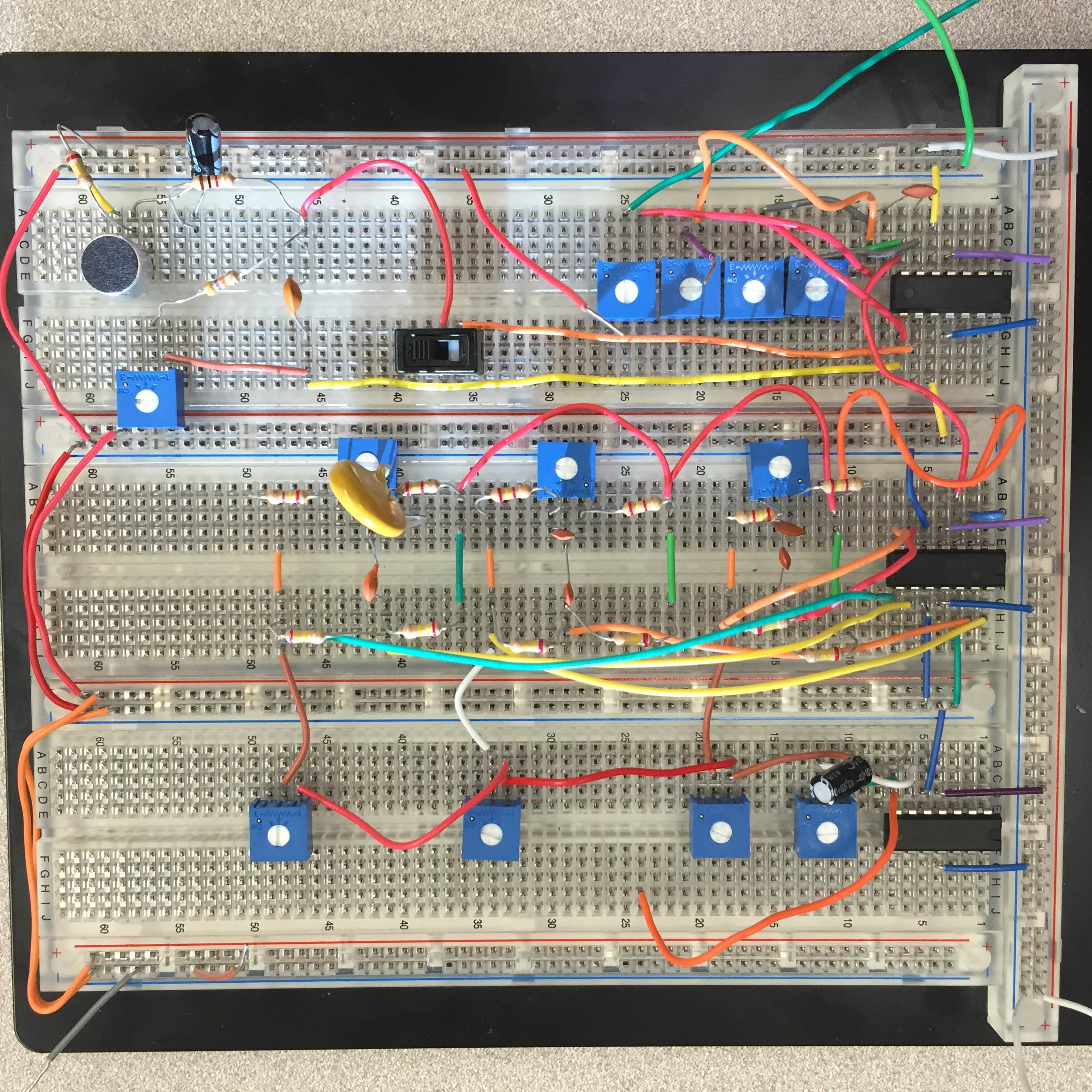
The final lab project for one of my electrical engineering classes, I constructed a simple audio mixer consisting of a microphone, two line inputs, a 3-band equalizer (around 250Hz, 1kHz and 4kHz) and output summing control. This project utilized my studies of analog filters, operational amplifiers and basic circuit design.
Blocked Circuits
- Microphone and Preamplifier
- Input Summing Amplifier
- 3-Band Equalizer Circuit and Summing Amplifier
Skills Developed
- Oscilloscope and Spectrum Analyzer
- Circuit Design
- Breadboard Construction and Testing
- Circuit Simulation and Modeling using SPICE
Completed December 2015
Wireless Broadband Networking installation technician
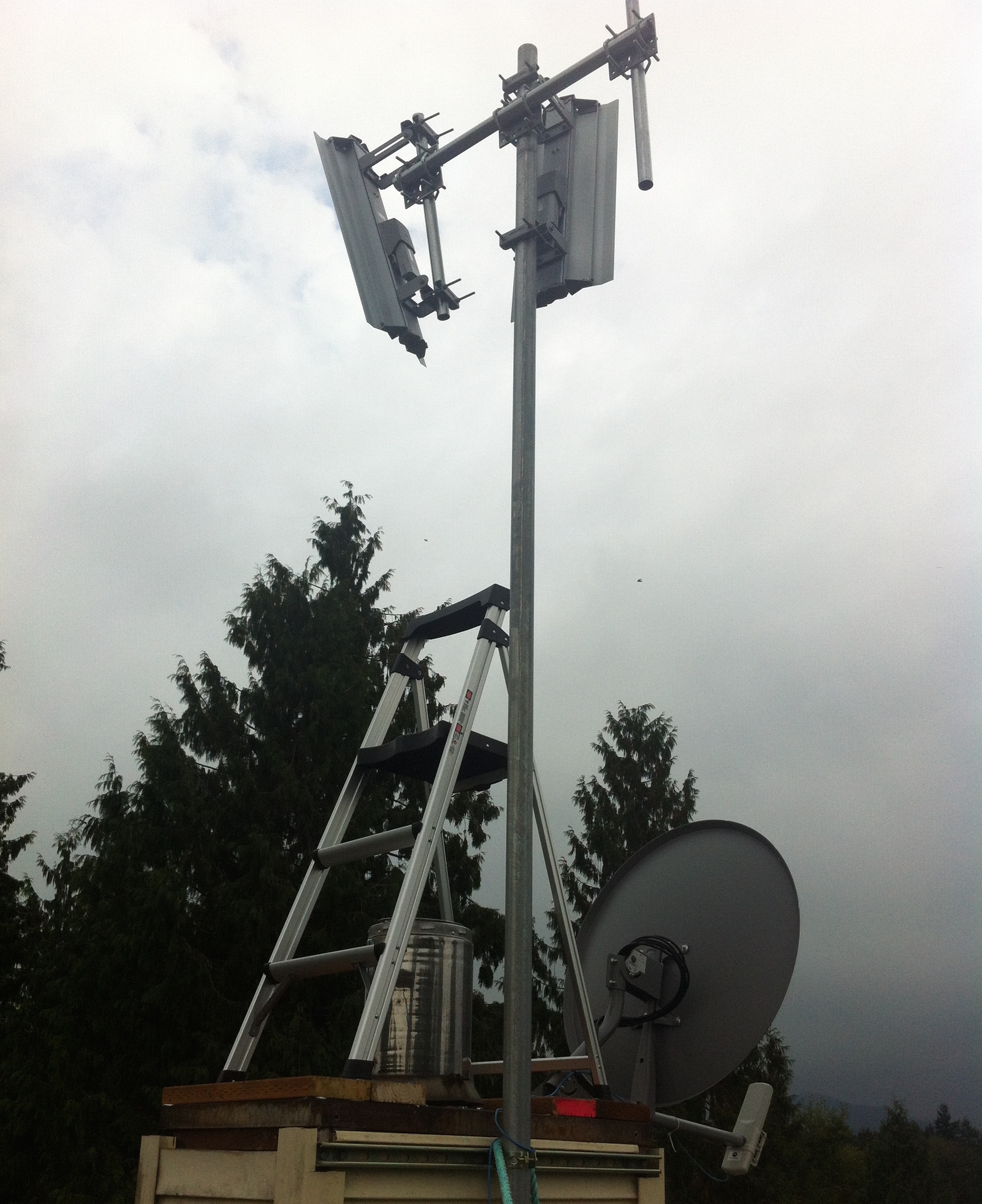
Objectives and Responsibilities
Working with Wesctom Broadband for one of their area expansions, I was responsible for assisting the senior technicians with the installation of an access point and the installation of service modules on the homes of new customers in the area. During the project I developed wireless network knowledge involving interference, broadcast frequency range and power characteristics, as well as transmitter/receiver configuration and troubleshooting.
Details
- 2.XGHz and 5.XGHz mixed frequency transmission
- Antenna power and projection area adjustments
- Configuration to avoid channel saturation and interference
August through October 2013
Additional Photos
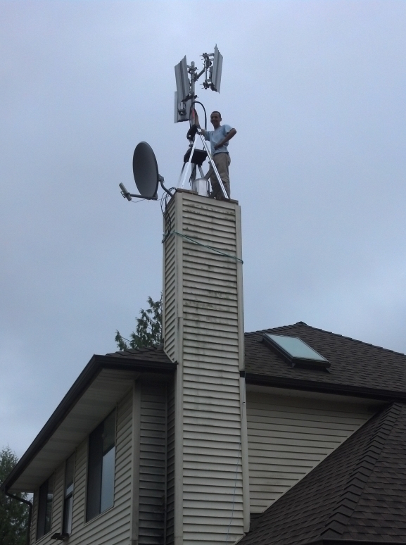
Myself, atop a chimney where I was installing a series of 2.4GHz high-power access points.
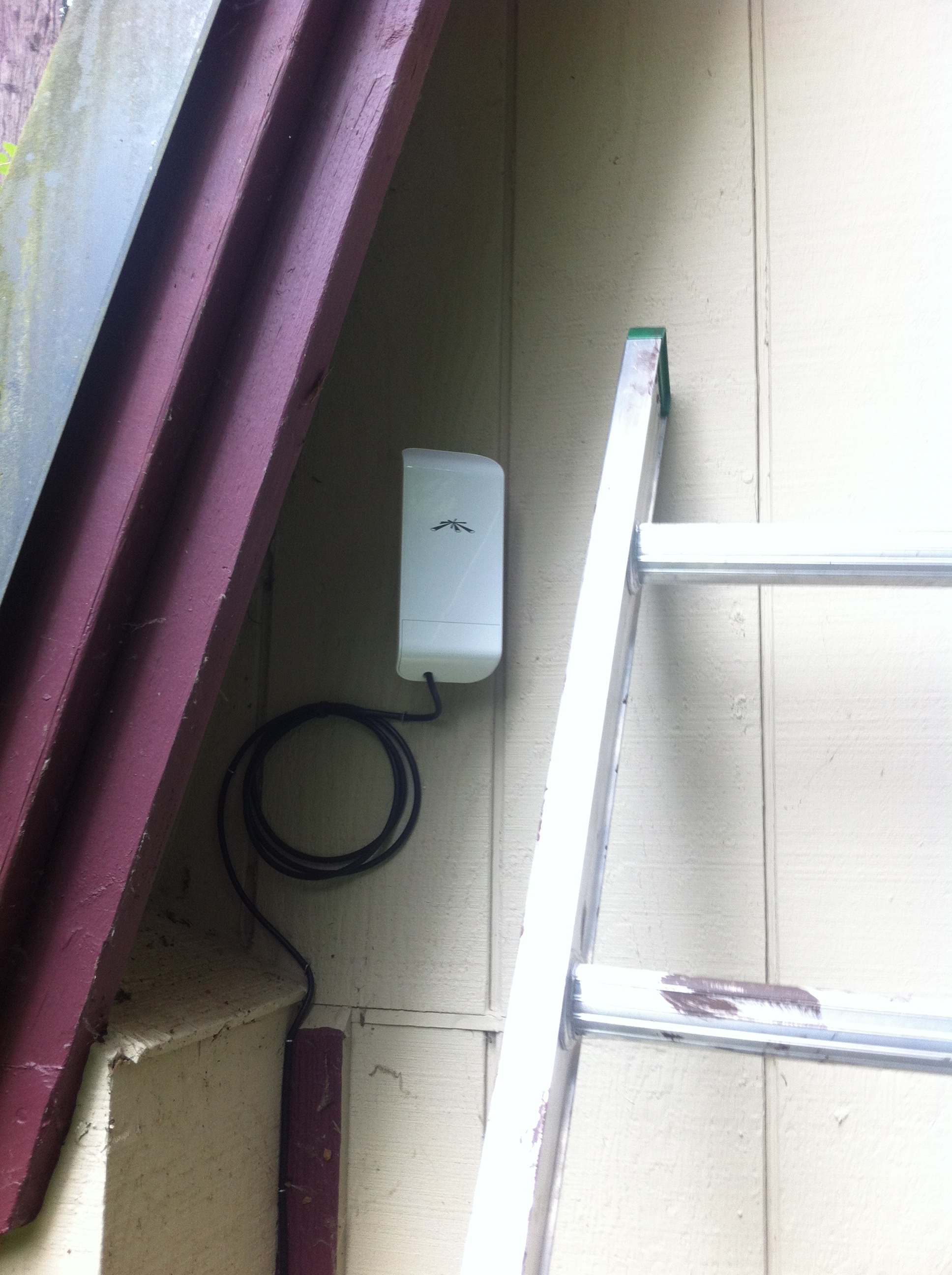
A service module I installed, hidden nicely beneath an eve in a nearby home.
Another installation on a home neighboring the access point from above.
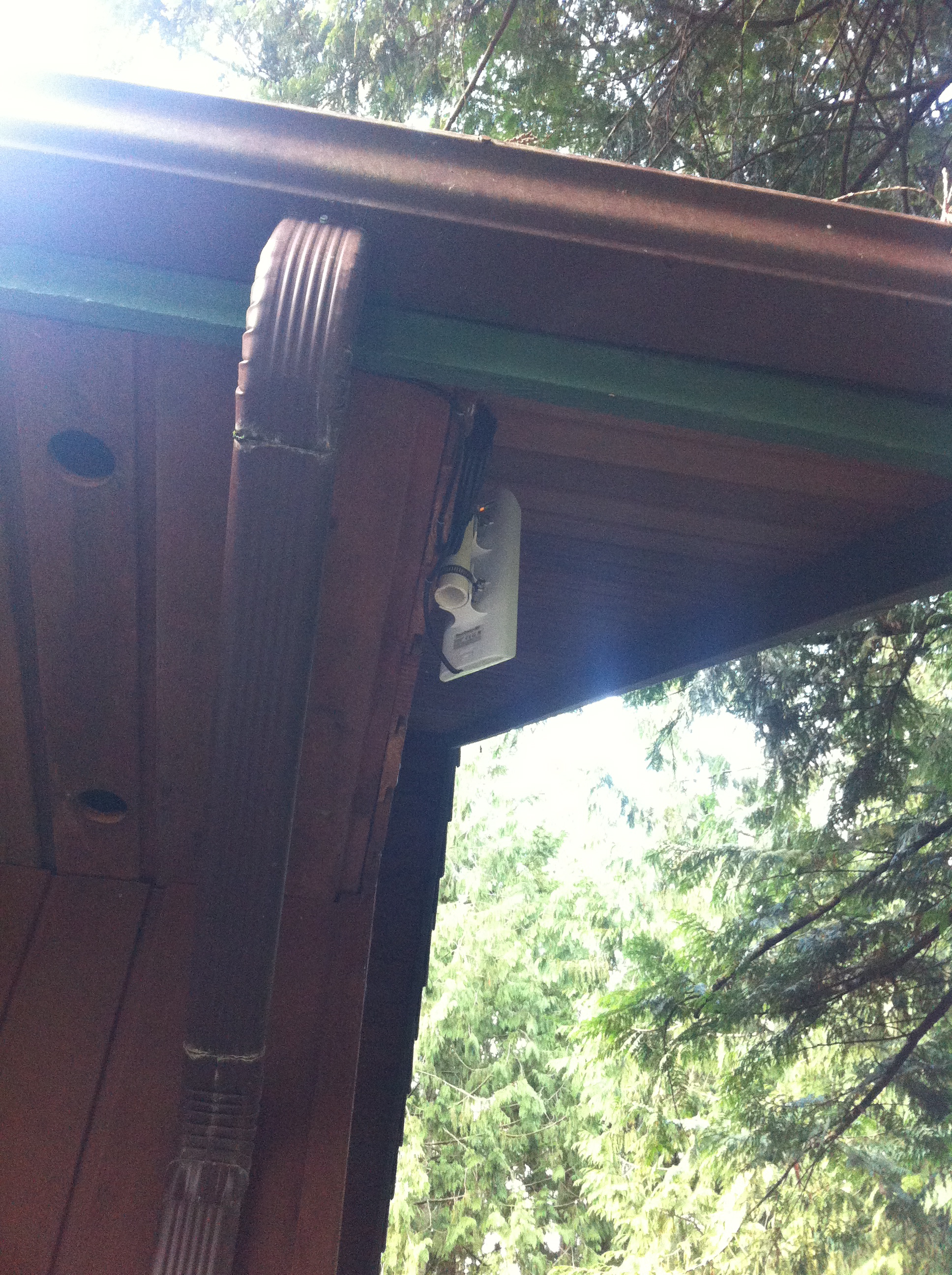
Service module tucked in behing an eve, pointing at the nearby access point.
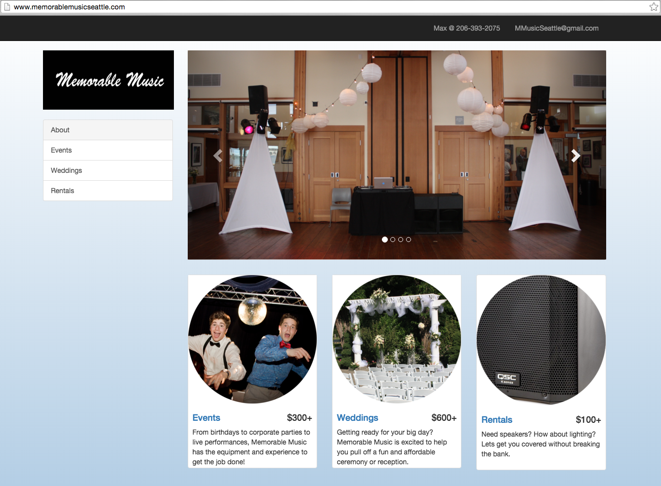
Web Design for MemorableMusicSeattle.com
Project Description
After some coding classes and frustrating Google searches, I built this web site for my business to save costs and expand my skill-set. Most of the pages are built using Bootstrap .css and .html elements, with layout, content and navigation modifications to create what can be seen live at Memorable Music Seattle!
Emphasized Skills
- Mark-up with HTML & CSS
- Basic Web Design
- Event Media Presentation
Completed November 2015
Custom Speaker Flyware for a QSC K12 active loudspeaker
Overview
In an effort to provide better sound quality at larger events by improving the dispersion of the speaker, I designed and constructed an aluminum T bracket to mount to the top of the speaker, with a small piece of chain attaching to the rear to maintain a desired angle. The two different sizes of clamp used to fasten the speaker and mount to the trussing also gives the speaker-mount system the proper downward angle to project sound evenly across larger crowds. Aerial mounting also eliminates the need for speaker stands, cleaning up the set-up process and improving the 'look' of the overall audio system.
Process
- Design the optimal orientation based on conical speaker dispersion of 75 degrees at 8 - 12 feet.
- Cut and weld aluminum 'T' brackets
- Attach clamps and safety cable
Completed June 2013
Photos
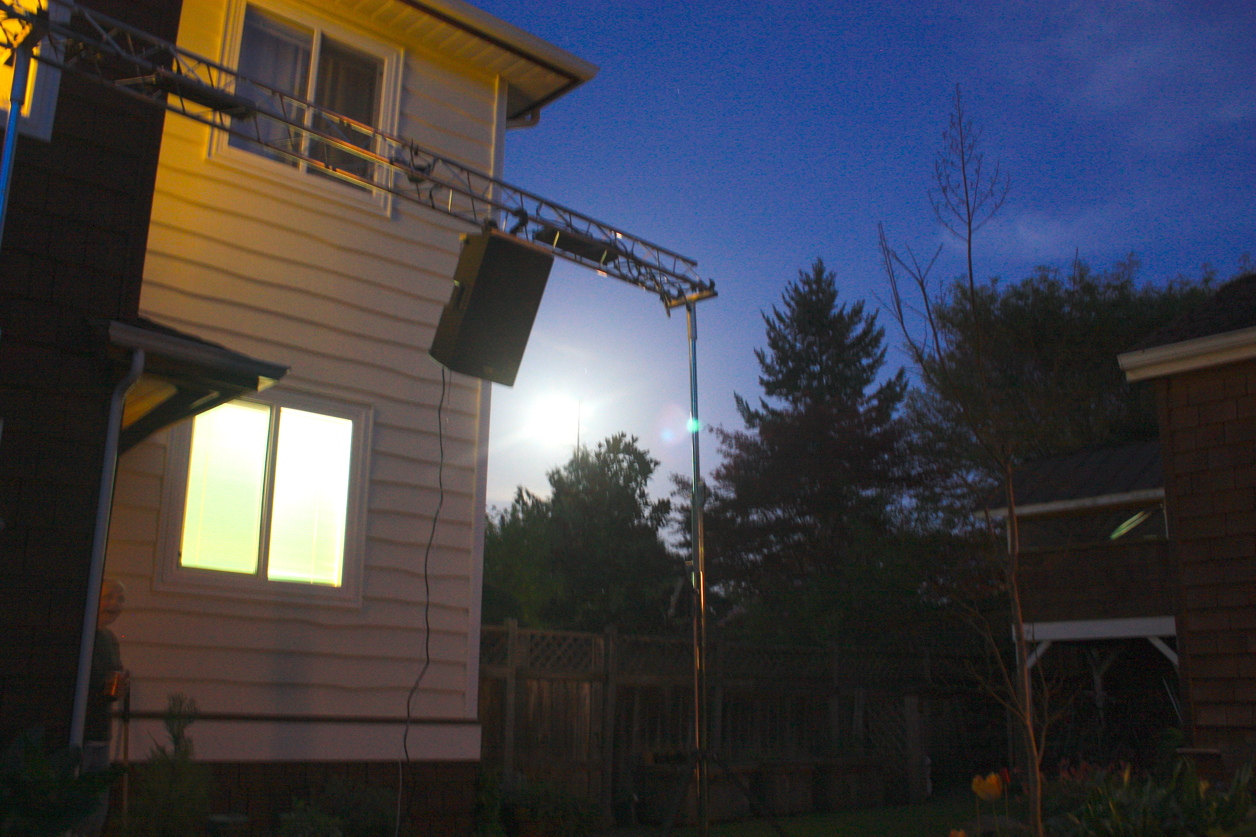
Standalone QSC k12 flown from my trussing system.
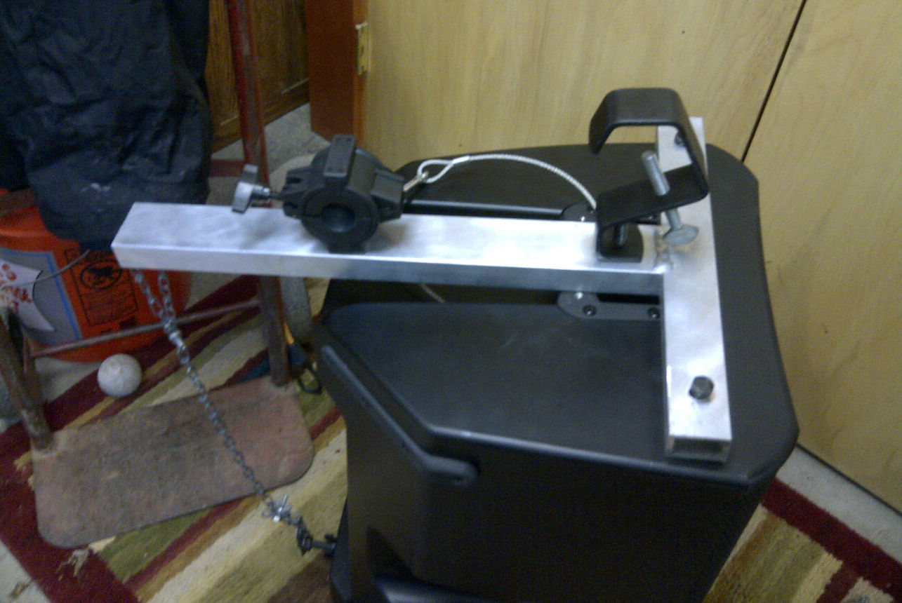
An up-close look at the completed bracket with mounting hardware and safety cable attached.
Electronics Repair fixing up a DJ mixer
Repair Description
Purchasing this used mixer from Craigslist, I anticipated some work. The headphone jack was loose and intermittent. The cue buttons and faders were also wearing out. The buttons had broken so they didn't bounce back when pressed. Eager to solve the problem myself, I pulled a 1/4 inch headphone jack out of an old receiver and matched the pin configuration, installing it in the mixer. I then repaired the buttons where a small flange had broken. Once done, I reassembled the mixer and tested it out!
Emphasized Skills
- Troubleshooting and identifying bad components
- Board level soldering
- Creative problem solving
Completed Summer 2011
Gate Welding Project Creative design and steel construction
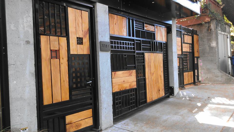
Project Summary
A summer project completed with an independent artist in Burien, myself and another worker were presented with metal frames to fill in with increasingly smaller rectangles so that a grapefruit would not fit through. After sketching basic patterns and welding grids, we constructed the gates weld-by-weld, sealing every connection, polishing the final product to be painted and fitted with the wood panels seen in the photo.
Objectives
- Design within specifications and constraints
- Building from sketches and plans
- Welding with a variety of gauges simultaneously
Completed August 2014
More Photos
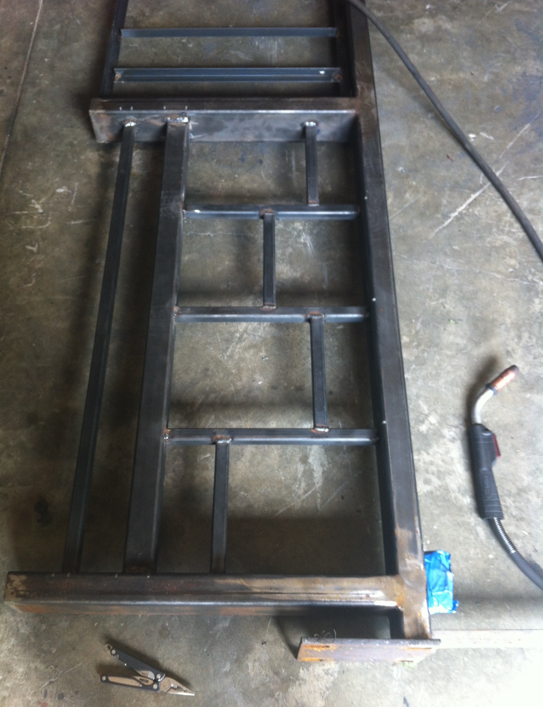
Preliminary welds before going all the way around the tube and brushing or grinding.
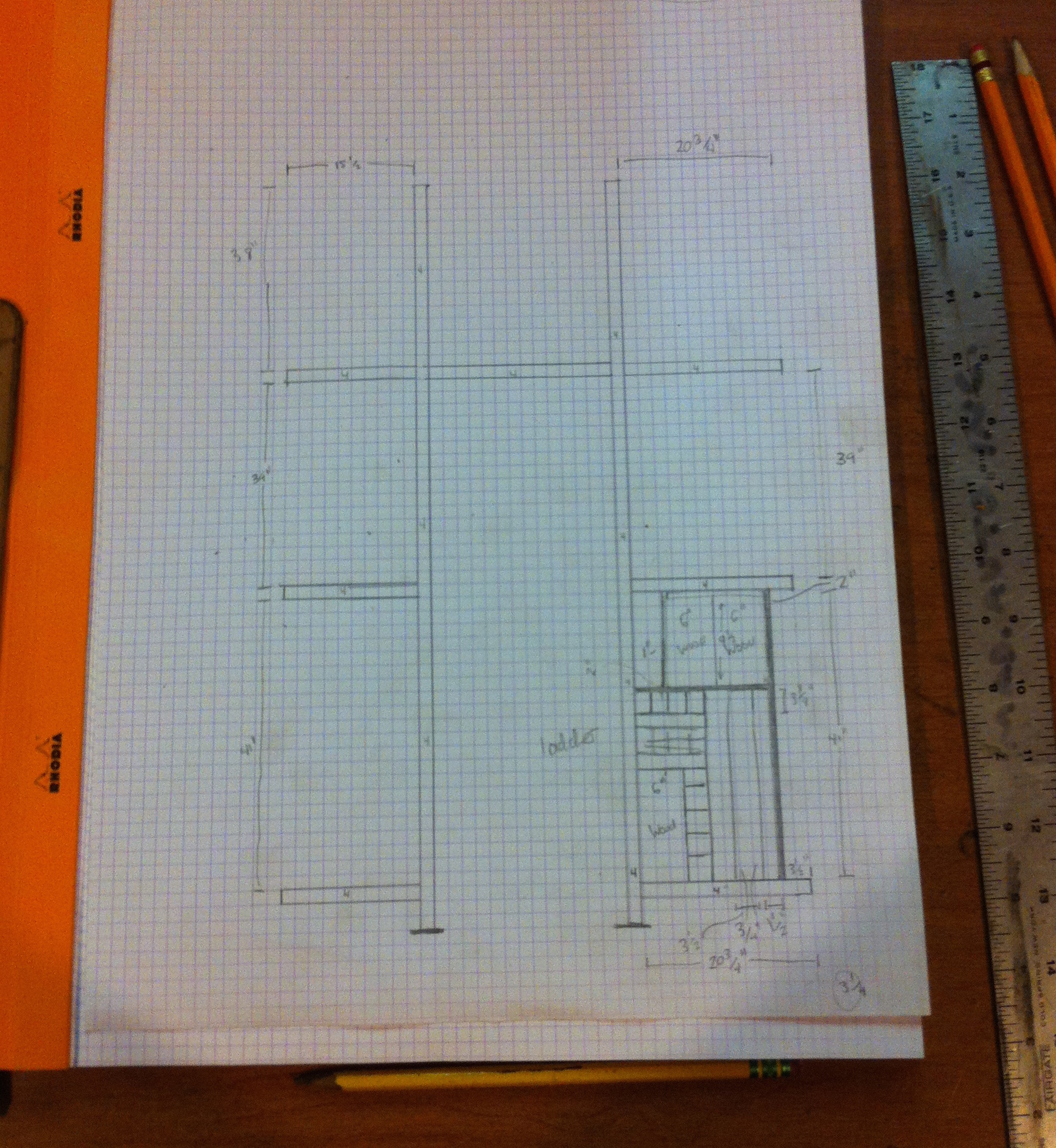
Paper sketch of a section before construction.
One of the frames being filled in by increasingly smaller rectangular spaces.
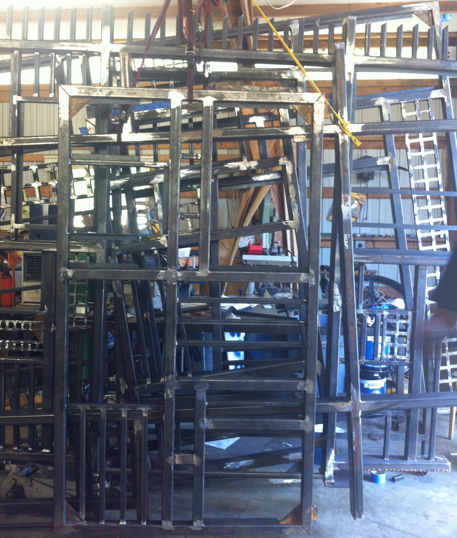
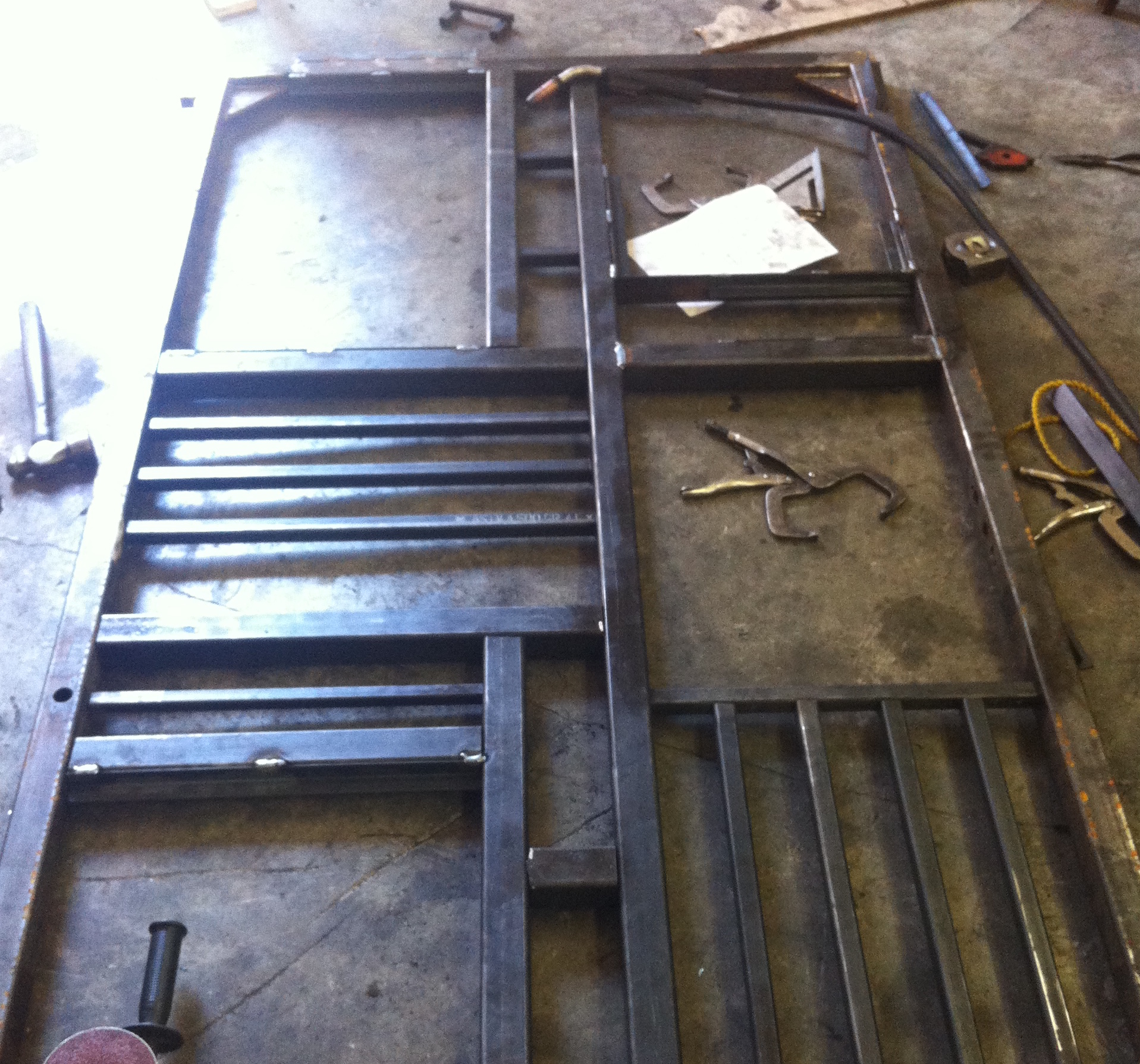
Partially complete frames hang in the shop in between work days.
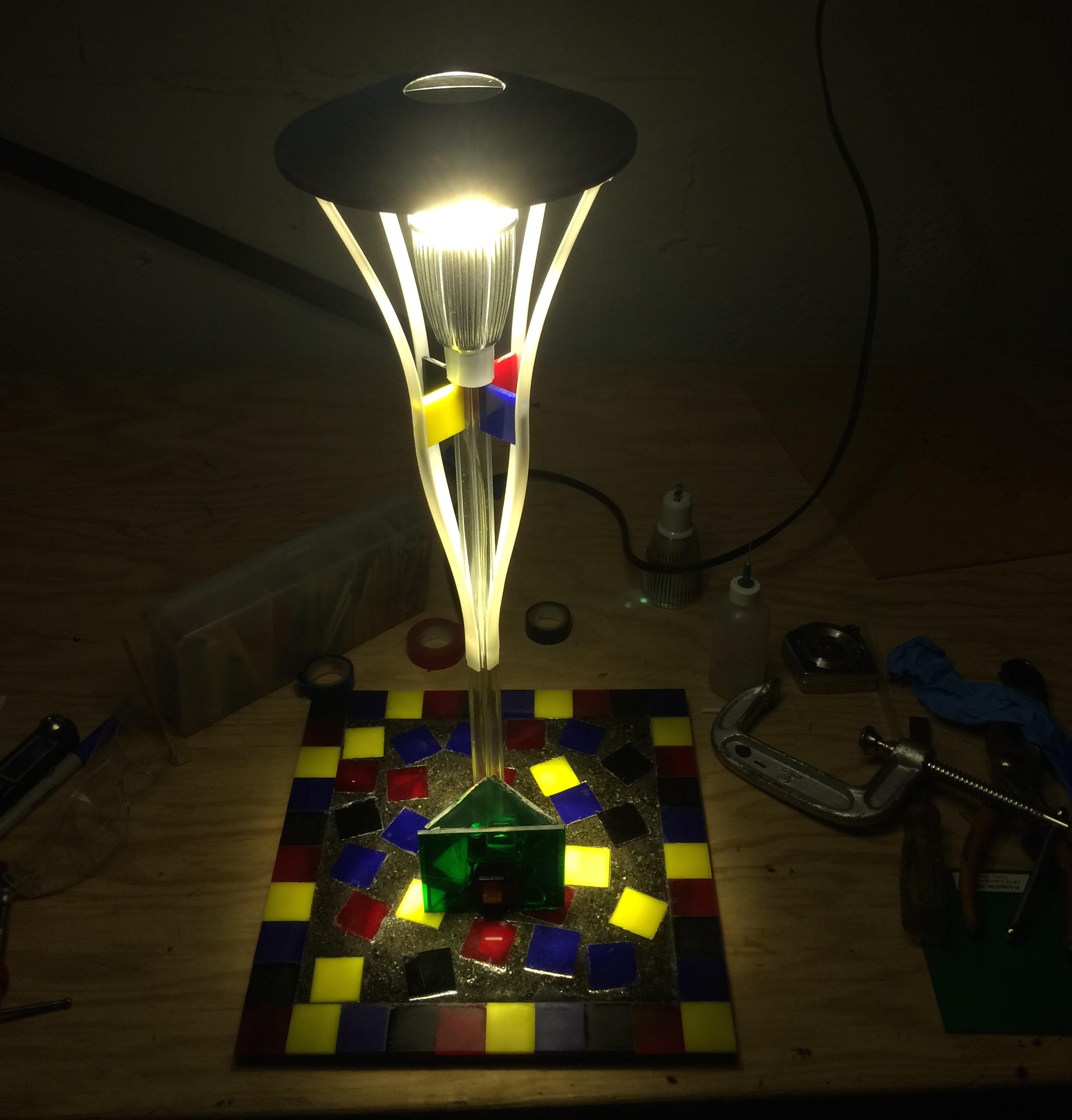
LED Desk Lamp cut, glued, soldered and screwed from scratch
Overview
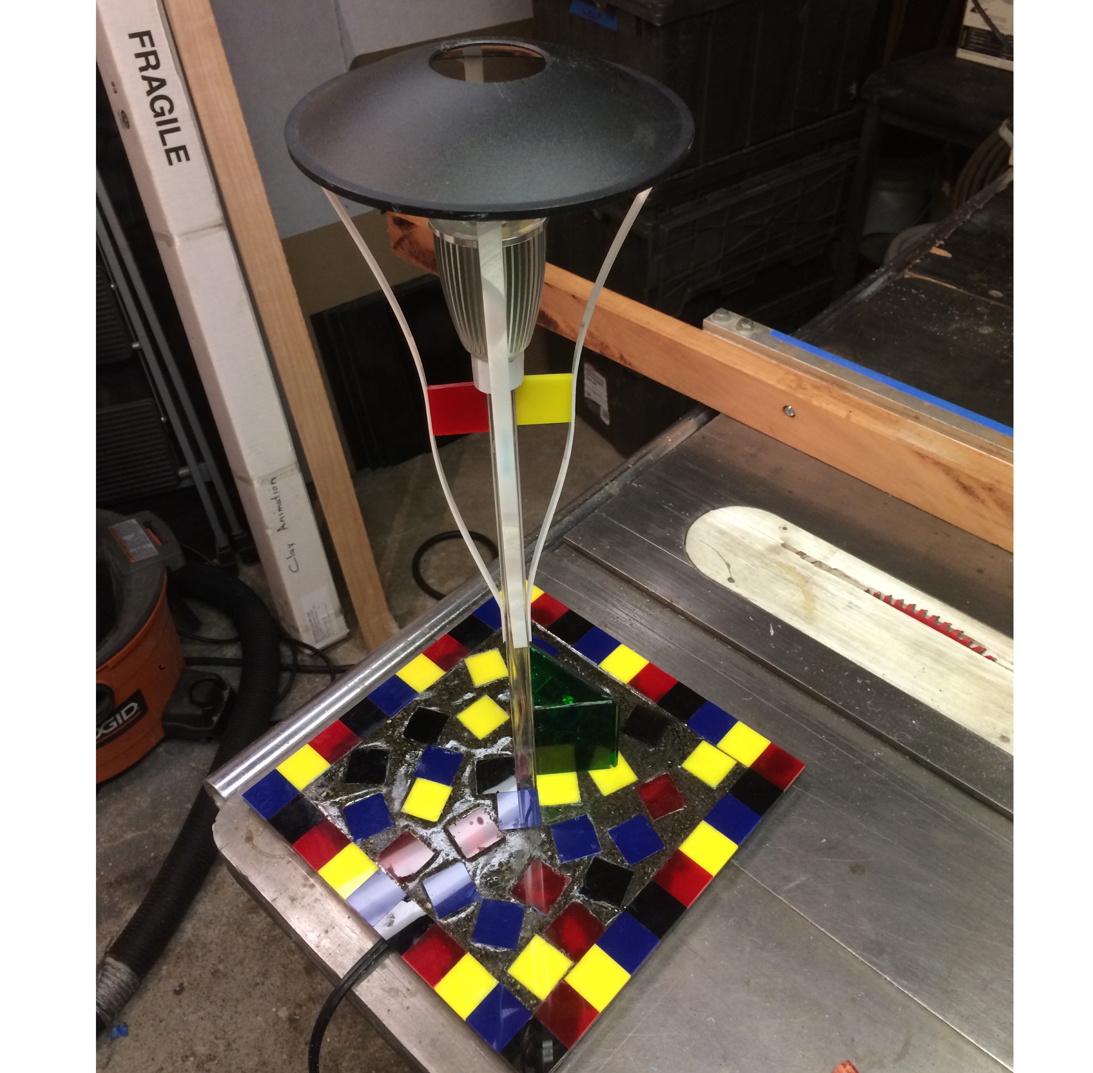
Lamp making is an incredibly enjoyable process. Working with different inanimate materials - some electrical, others chemical and physical - there is a satisfaction to combining the elements into a luminaire. The materials were recycled from other projects. All cuts were made with precision saws and routers to build the patterned structure. The white plastic strips running up the outside were heated and bent in order to be adhered to the body of the lamp. The electrical components came from a 120VAC 8W LED kit assembled to fit the nicely in the center, projecting light through a reflective dish that also directed much of the light downwards at the lamp's base.
Methods
- Precision Plastic Cutting and Adhesion
- Clear Sand Casting with a 2-Part Mix
- Wiring and Soldering
Materials
- 0.125" Red, Blue, Yellow and Black Acrylic
- 0.0625" White Acrylic
- 0.25" Clear Square Tube
- Shallow Reflector Dish
- ClearCast casting plastic
- Sand
- 12VDC 8W 750lm LED Lamp
- Rectifier/Transformer Circuit
- Switch and AC power cable
Completed July 2015
More Photos
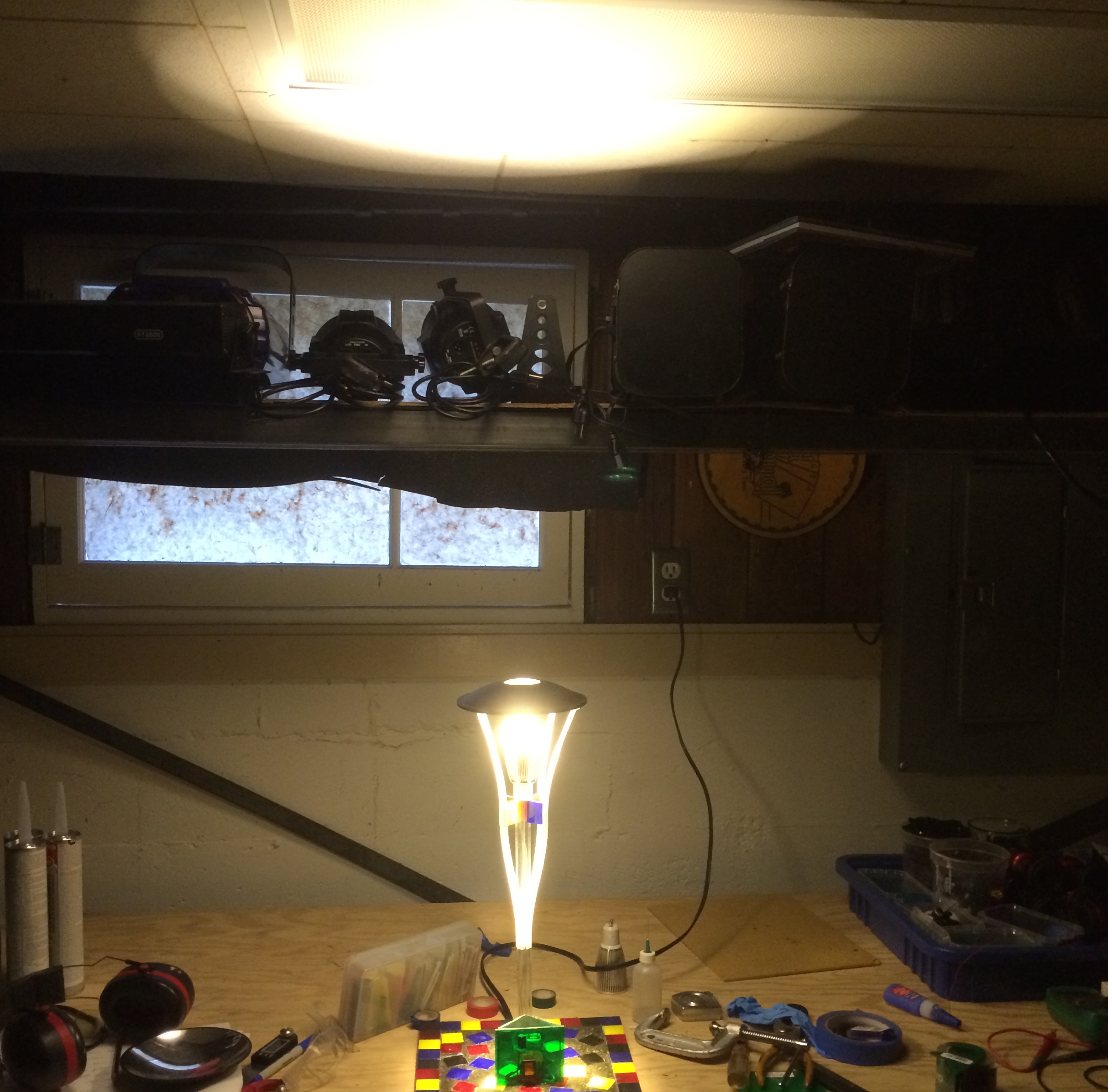
Finished lamp from a distance, demonstrating the pattern on the ceiling above.
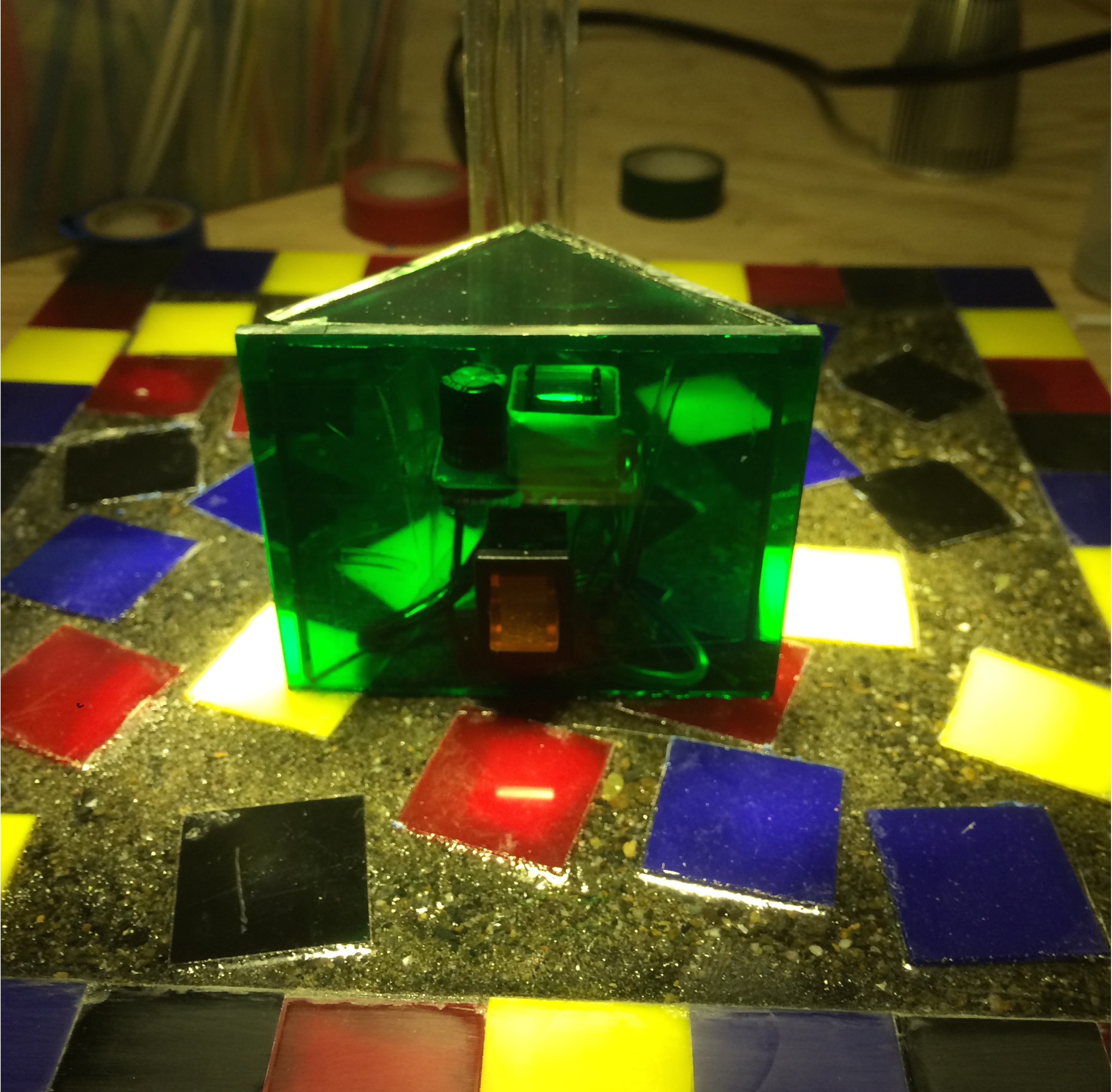
The lamp's switch in clear plastic casing as seen from the front.
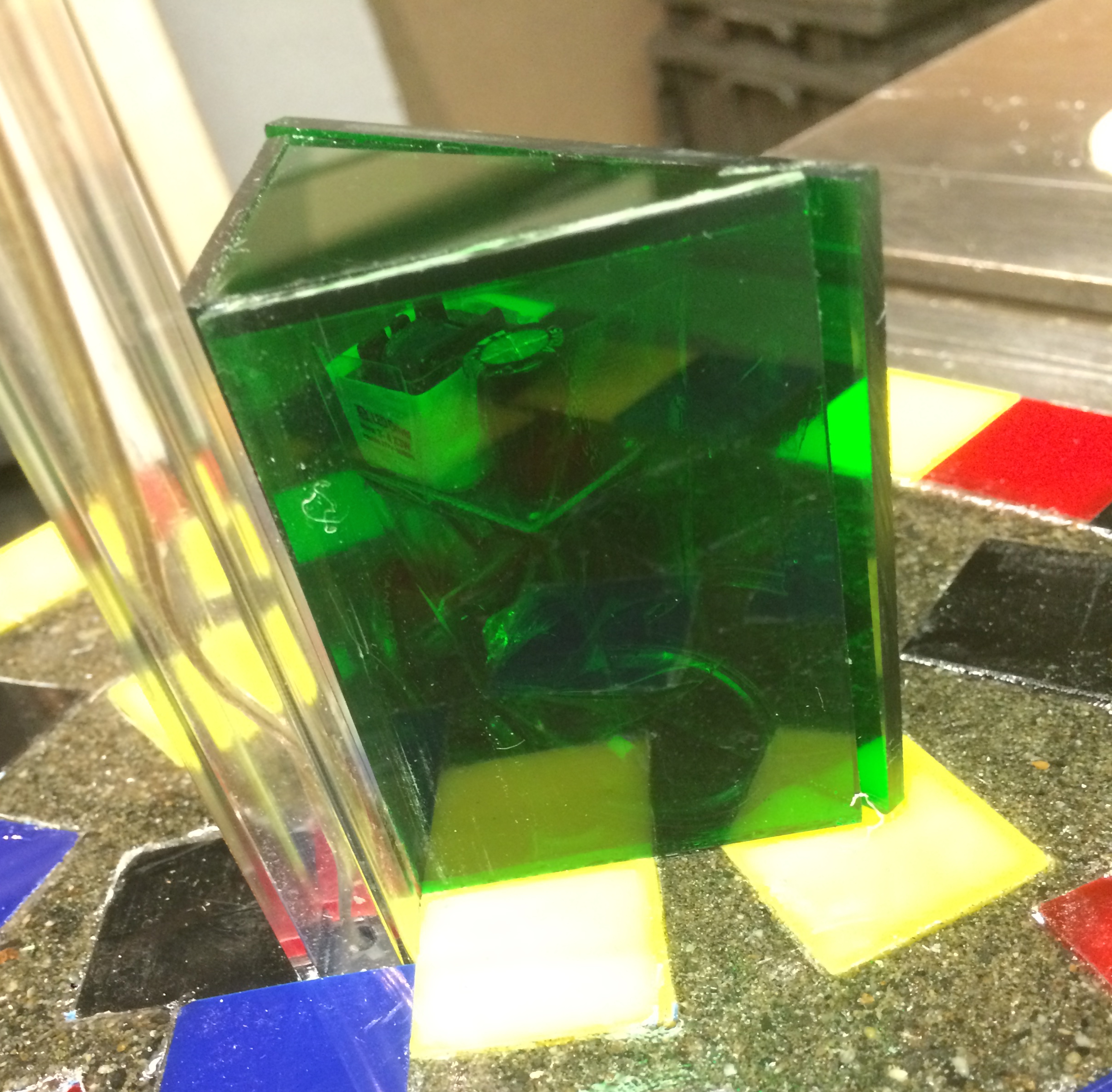
Through the clear green Acrylic, the transformer and capacitor powering the LED can be seen.
This top down view from a back corner of the lamp shows the white glowing trim and reflector dish.
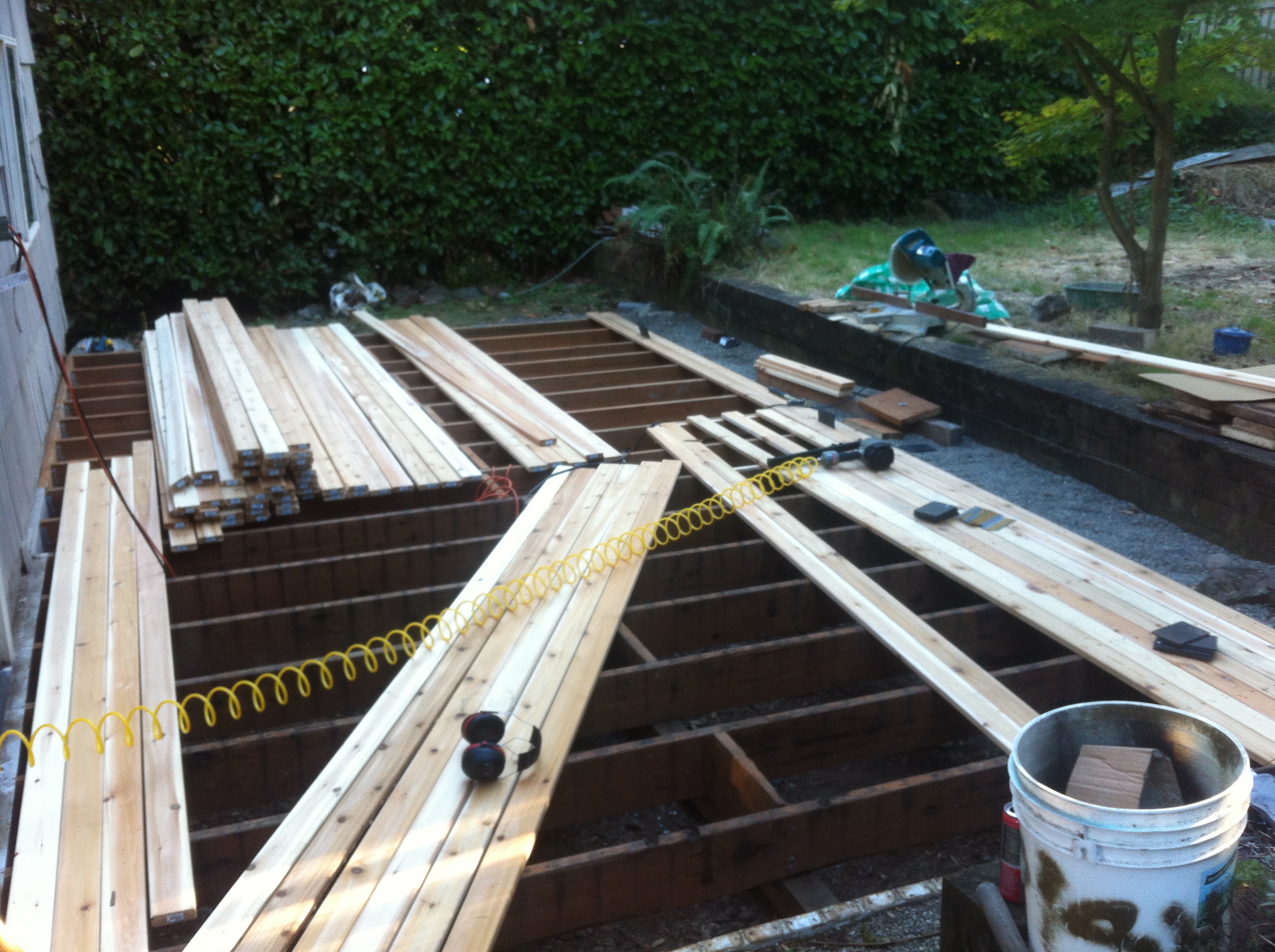
Cedar Deck Remodel Removal and reconstruction of deck at Wallingford house
Work Completed
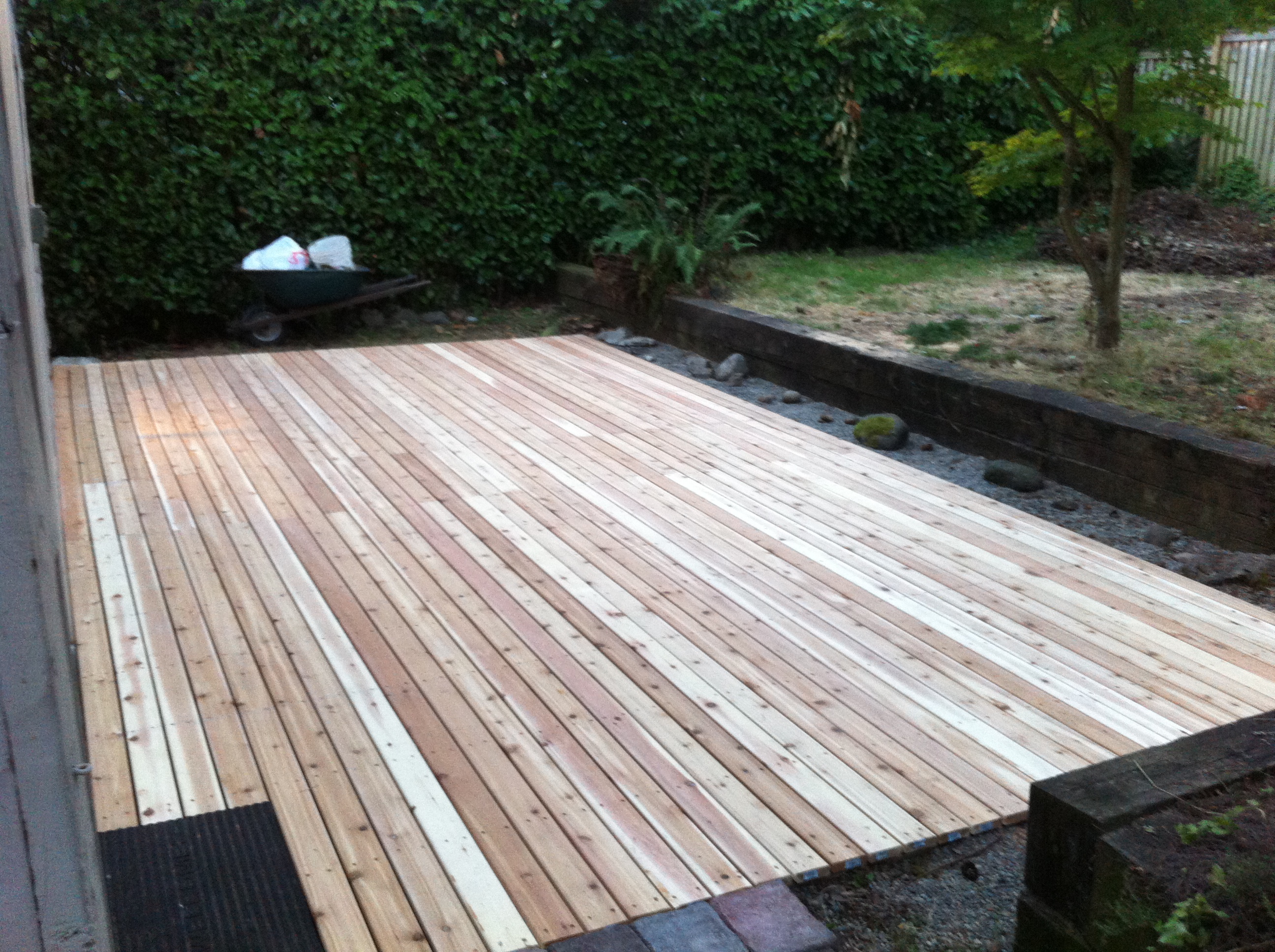
Accumulation of debris and an old hot-tub caused excessive moisture damage and rot to the original deck. I was hired by the homeowners to remove the old deck and hot-tub, rebuilding the footprint with a new 12" by 20" Cedar deck. Over the course of 2 weeks, I was able to clear the space, re-build and level the joists and footings supporting the deck and install new cedar surface planks. The final product is visible on left.
Steps
- Removal of Existing Deck
- Design of a new deck to fit the space and grade changes
- Construction of new foundations and supporting joists
- Planking the frame and landscaping the surrounding area
Completed August 2014
Additional Photos
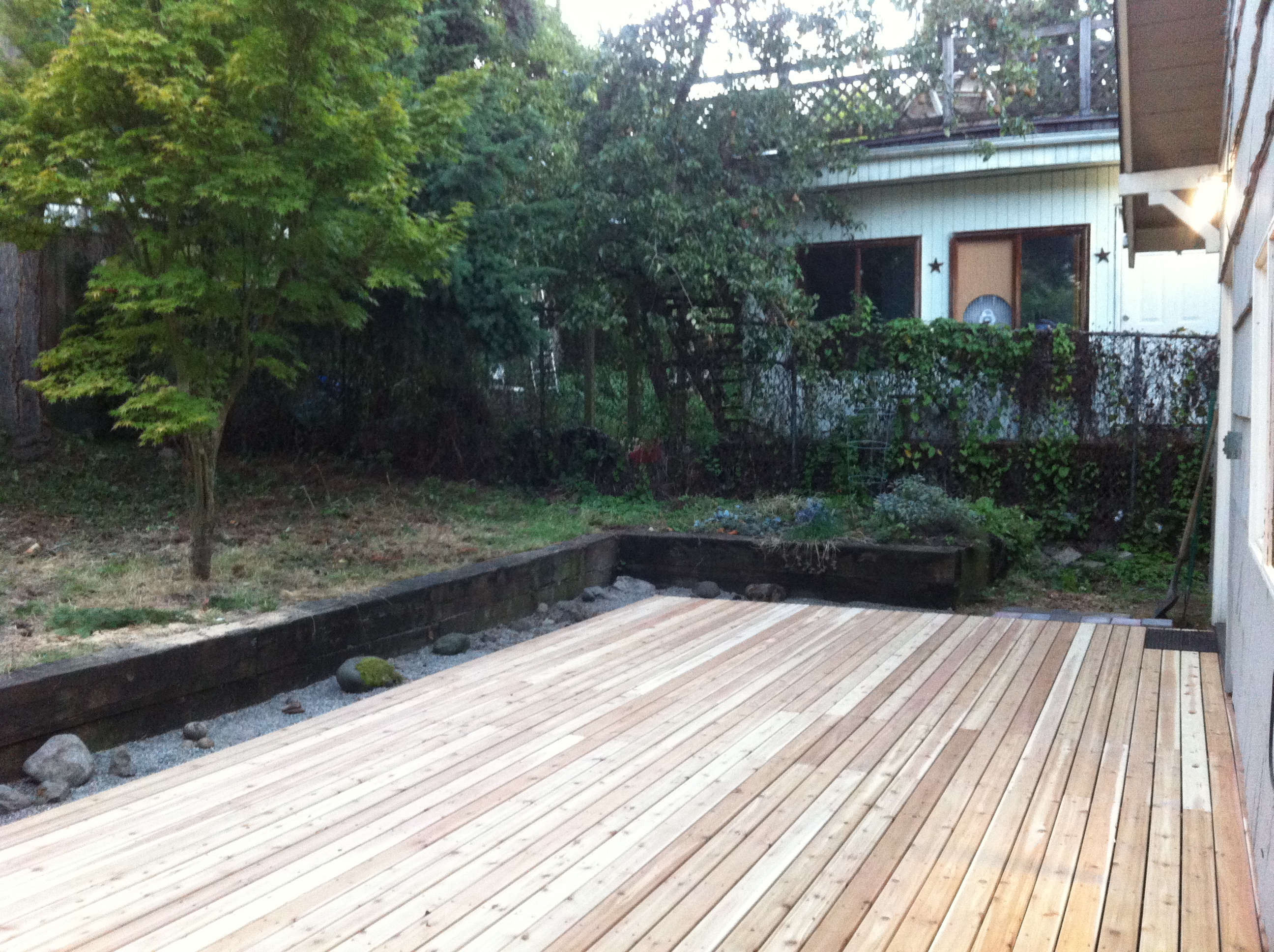
Completed deck from opposite side. Also exhibits a small rock garden on the outer edge.
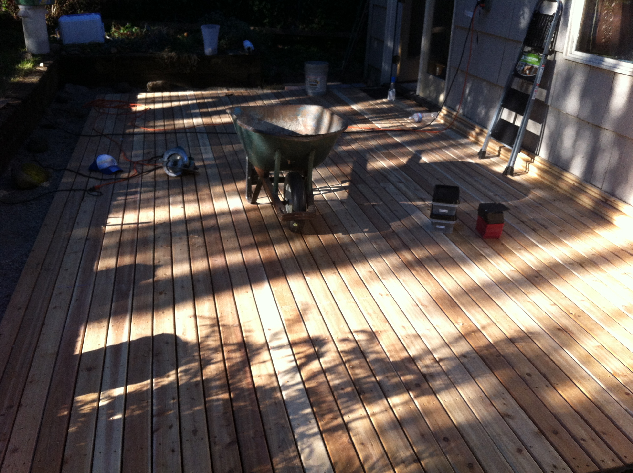
Final stages of completion.
Decking rests on the completed frame, ready to be installed.
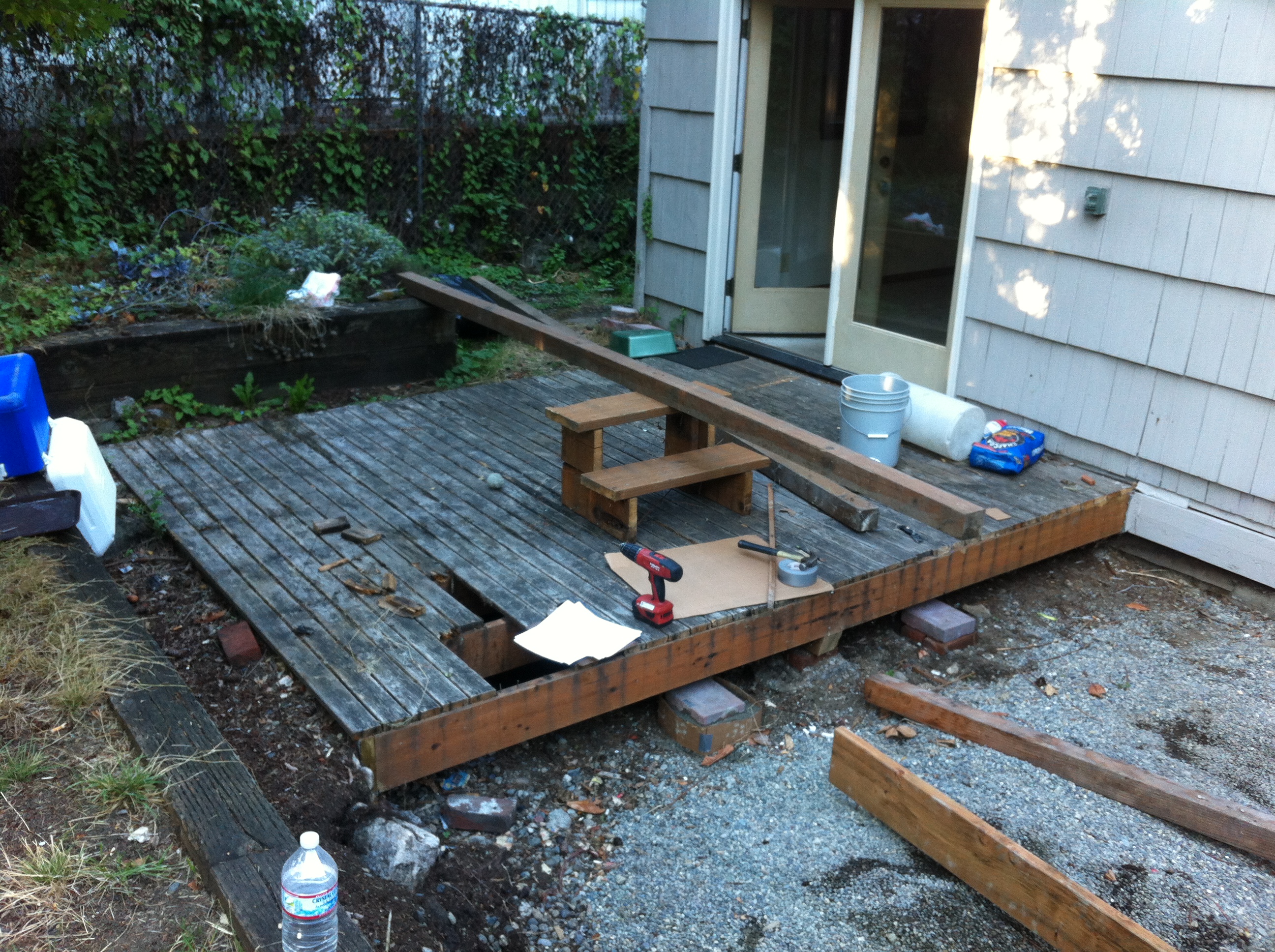
A portion of the old deck, with holes where people had stepped through.
Fiberglass Repair Structural patching small boats
Details
As part of my duties at Sail Sand Point, I was responsible for in-house equipment maintenence. Part of maintaining a fleet of over 200 boats involves the inevitable damage to hulls and rails on the fiberglass boats. One of the older boats, seen hanging in the first photo hit a submerged object and suffered serious damage that could only be repaired by cutting away the mangled fiberglass and re-building the boat in that area. This process
Methods
- Removal of the damaged material
- Adding star-board stringers wrapped in fiberglass to reinforce damaged area
- Filling in repair to match the hull contour
- Applying layers of fiberglass cloth to increase strength
- Sanding and smoothing final product
- Gel-Coating the patch to blend it with the white hull (not pictured)
Completed February 2014
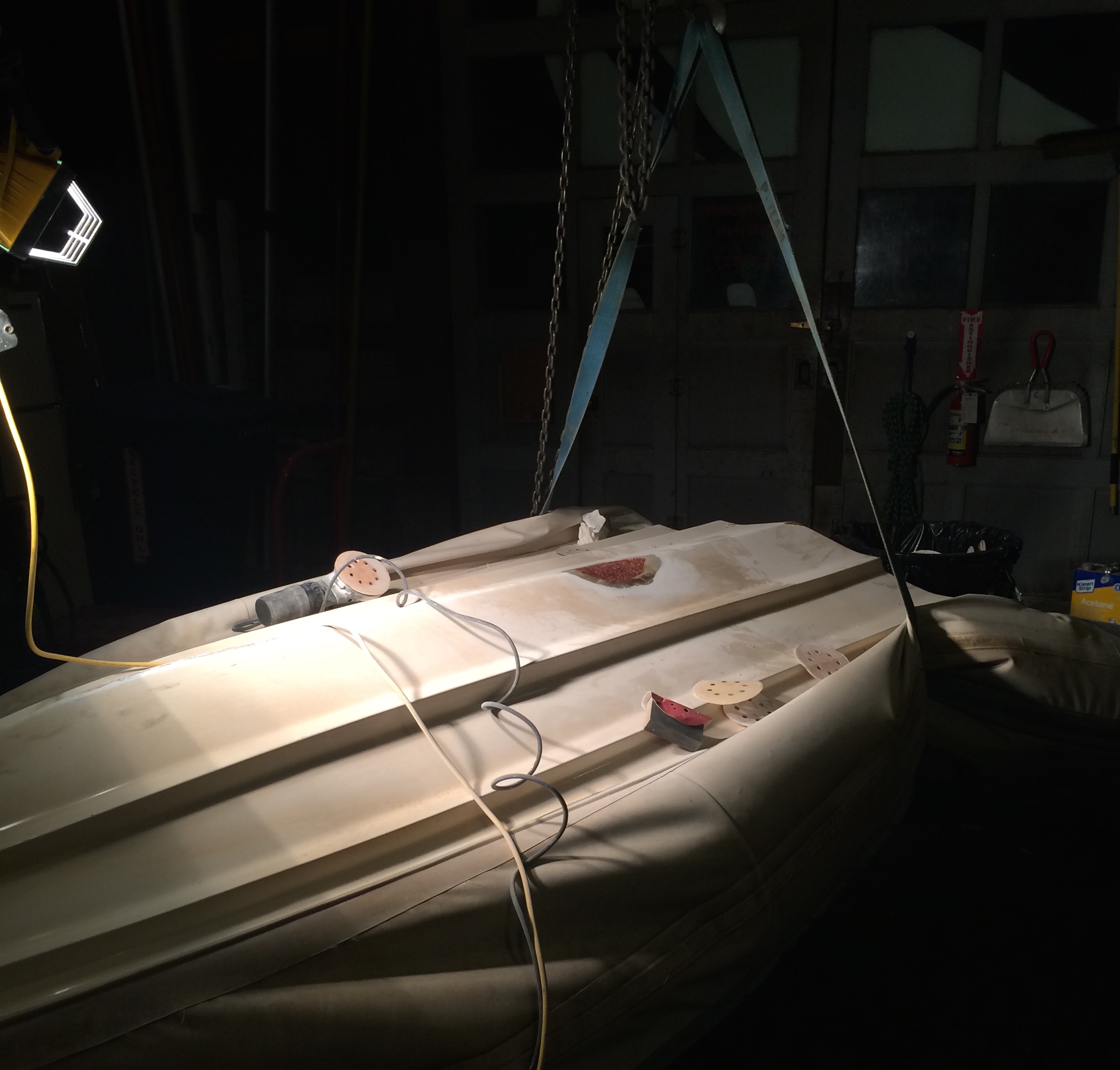
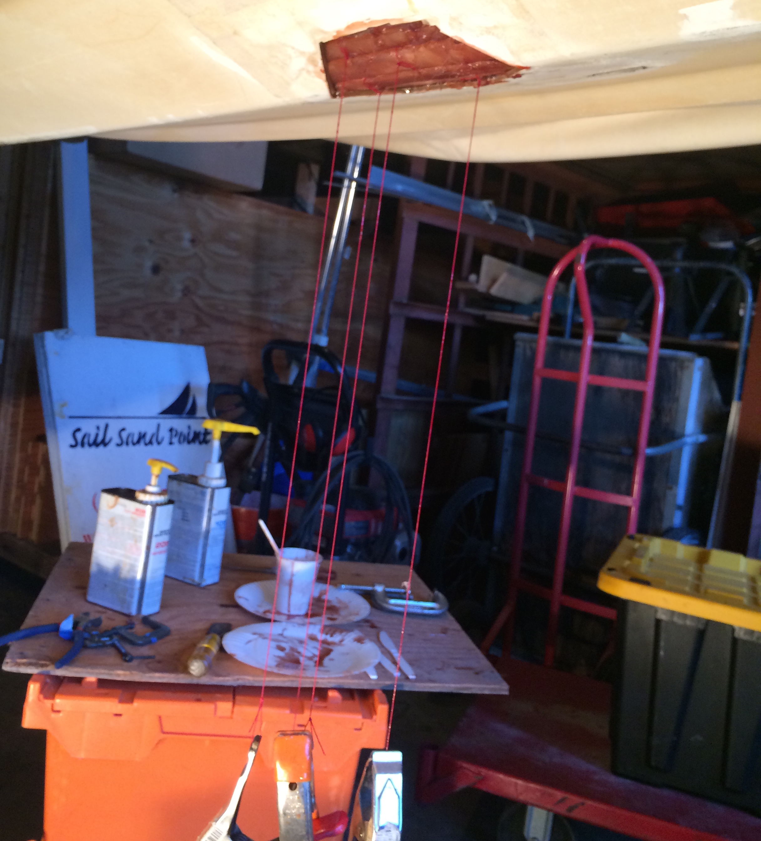
Underside of the suspended boat, where stringers are seen being pulled down by clamps. The stringers add structural stability to the large patch in the hull.
Once reinforced, a fiberglass filler is mixed with the resin and used to build up the patch area to match the contour of the hull.
After filler comes layers of fiberglass. Here a bi-directional cloth is used for convenience. The image above shows the first hardened layers of fiberglass on the patch.
The last layers of patch cloth dry in preparation for sanding and the application of Gel-Coat, a paint like finish to protect the fiberglass.